Download
1 / 26
260 likes | 389 Vues
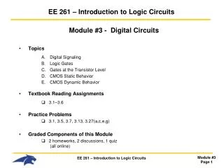
EE 440 LOGIC CIRCUITS I. “BCD Adder” Prepared By: Güray GÜRKAN, Ph.D. Previous Experiment: 4 bit Parallel Adder. x 0 x 1 x 3. PARALLEL ADDER. X 4-bits. s 0 s 1 s 3. S 4-bits. y 0 y 1 y 3. Y 4-bits. Previous Experiment: 4 bit Parallel Adder. Previous Experiment:

E N D
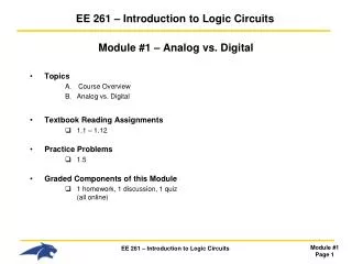
EE 440 LOGIC CIRCUITS I “BCD Adder” Prepared By: Güray GÜRKAN, Ph.D.
Previous Experiment: 4 bit Parallel Adder x0 x1 x3 PARALLELADDER X 4-bits s0 s1 s3 S 4-bits y0 y1 y3 Y4-bits
Previous Experiment: 4 bit Parallel Adder
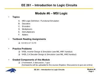
Previous Experiment: 4 bit Parallel Adder X0 y0 S0 S1 S0 C1 HA FA X1 y1 S1 C2 FA S2 X2 y2 S2 C3 S3 C4=S4 FA x3 y3
4 bit Adder Chip: 7483 Sum(S4,S3,S2,S1) Number 1(A4,A3,A2,A1) Number 2(B4,B3,B2,B1) Carry IN Carry OUT
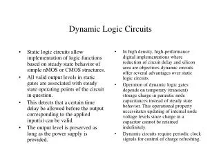
How can we use this chip as BCD adder? BCD = Binary Coded Decimal In decimal mode, maximum number is “9” IF Sum > 9, we should have a carry*
BCD Adder: Carry Circuit S2 S1 1 1 1 1 S4 S3 1 1 (S2 AND S4) OR ( S3 AND S4)
BCD Adder: Carry Circuit Now add this subcircuit
(S2 AND S4) OR ( S3 AND S4) Carry Sub-Circuit
DEC HEX 8 8 8 10 C + 0 10 12 C + 2 12 16 C + 6 C + 0 18 C + 8 C + 2
Result: If we add “6” to a 4 bit sum Z, where Z>9, the first digit will be the decimal representation of the summation.
MSI BCD ADDER n- dijitlik olana genelleştirme nasıl yapabiliriz? İkili (binary) ve BCD toplayıcıların karşılaştırması? Ertuğrul Eriş
İKİ BİTLİK ÇARPMA DEVRESİ Ertuğrul Eriş
MSI KARŞILAŞTIRMA DEVRESİ (COMPARATOR) Girişler A = A3 A2 A1 A0 ve B = B3 B2 B1 B0 A < B için Ç1 = 1 Ç2 = 0 Ç3 = 0; A > B için Ç1 = 0 Ç2 = 1 Ç3 = 0; A = B iken Ç1 = 0 Ç2 = 0 Ç3 = 1 Xi = AiBi + A'iB'i i = 0,1,2,3 A = B → Ç3 = x3 x2 x1 x0 = 1 A > B → Ç2 = A3B‘3 + x3 A2B‘2 + x3 x2A1B‘1 + x3 x2 x1A0B‘0 A < B → Ç1 = A‘3B3 + x3 A‘2 B2 + x3 x2A‘1B 1 + x3 x2 x1A‘0B0 Klasik yöntemle sentez yapsak ne olur du? Çıkış iki değişkenle ifade edilebilir mi? Üç değişkenli çıkış’ın getirdiği yarar ve ödenen bedel nedir? Çıkarma işleminde karşılaştırma devresi neden düşünmedik? Ertuğrul Eriş
MSI KARŞILAŞTIRMA DEVRESİ (COMPARATOR) Girişler A=A3A2A1A0 ve B=B3B2B1B0 A < B için Ç1 = 1 Ç2 = 0 Ç3 = 0; A > B için Ç1 = 0 Ç2 = 1 Ç3 = 0; A = B iken Ç1 = 0 Ç2 = 0 Ç3 = 1 Xi = AiBi + A'iB'i i = 0,1,2,3 A=B Ç3 = x3 x2 x1 x0 = 1 A>B Ç2 = A3B‘3 + x3 A2B‘2 + x3 x2A1B‘1 + x3 x2 x1A0B‘0 A<B Ç1 = A‘3B3 + x3 A‘2 B2 + x3 x2A‘1B 1 + x3 x2 x1A‘0B0 Ertuğrul Eriş
MSI ÇÖZÜCÜLER (DECODERS)3X8 Ertuğrul Eriş
MSI ÇÖZÜCÜLER (DECODERS)-2(2X4 ENABLE GİRİŞLİ) Active (0) output 0 Ertuğrul Eriş
ÇÖZÜCÜLERDE KAPASİTE ARTTIRIMI (2 tane 3X8 likten bir 4X16 lık ) • Enable girişinin yorumu? • çalıştırıp/çalıştırmamam kontrolü • kapasite arttırımı Ertuğrul Eriş
DECODER UYGULAMASI:TAM TOPLAMA DEVRESİ C=Σ3,5,6,7 S=Σ1,2,4,7 Hangi çözücü çıktıları ile fonksiyon oluşturuluyor? Çözücülerin yazılımın donanımı kontrol aracı olarak düşünebilirmiyiz? Ne yarar sağlamış oluruz? Ertuğrul Eriş