Download
1 / 38
380 likes | 516 Vues
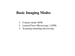
Basic Imaging Modes. Contact mode AFM Lateral Force Microscopy ( LFM) Scanning tunneling microscopy. Review last lecture. Position sensitive Photo-detector. Summarize: Main components of AFM. AFM tip/cantilever assembly Force detection system Electronic Feedback system (Electronic Brain)

E N D
Basic Imaging Modes • Contact mode AFM • Lateral Force Microscopy ( LFM) • Scanning tunneling microscopy
Review last lecture Position sensitive Photo-detector
Summarize: Main components of AFM AFM tip/cantilever assembly Force detection system Electronic Feedback system (Electronic Brain) Scanner ( precise position control system) Vibration damping system
x1 x2 Force Detection system Hook’ law: F= - kx k: Spring constant of the cantilever Materials, and dimension of the cantilever k increases with lever thickness, decreases with lever length
Contact Mode The original AFM mode, providing topographic imaging and a gateway to advanced techniques. Contact mode is the basis for all AFM techniques in which the probe tip is in constant physical contact with the sample surface. While the tip scans along the surface, the sample topography induces a vertical deflection of the cantilever. A feedback loop maintains this deflection at a preset load force and uses the feedback response to generate a topographic image. Contact Mode is suitable for materials science, biological applications and basic research. It also serves as a basis for further SPM techniques that require direct tip-sample contact.
Atomic Force Microscopy Force mapping
Very rough surface Tip crashed or sample destroyed Smarter imaging ---Need a Feedback system
Piezoelectric Scanners (Scanning Mechanism ) Piezoelectric effect: piezoelectric crystals The electrical polarization produces is proportional to the stress and the direction. The polarization changes if the stress changes from compression to tension Reverse piezoelectric effect Materials: lead zirconate titanates ( Pb(Ti, Zr)O3) PZT type )
Review last lecture Youtube: AFM Principle - How AFM Works
Lateral Force Microscope ( LFM) Or Friction Force Microscope ( FFM) Langmuir-Blodgett single-layer thin film made of a mixture of behenic acid (BA) and diphenyl bis-(octadecylamino)phosphonium bromide (DPOP). Both topographic (left) and LFM (right) images were acquired simultaneously.
Lateral Force Microscopy (LFM) is derived from Contact Mode imaging. In Contact Mode, the vertical bending of the cantilever probe is measured as it scans across the surface. By also measuring the lateral bending of the cantilever, information regarding the surface friction characteristics of a sample can be determined. • Lateral forces can arise from changes in the frictional coefficient of a region on the sample surface or from onsets of changes in height. LFM is therefore useful for measuring lack of homogeneity in surface materials and producing images with enhanced edges of topographic features.
Contact imaging mode Advantages: Disadvantages:
Scanning Tunneling Microscopy (STM) • Tunneling current ( pA ~ nA) between tip and sample is exponentially dependent on their separation ( <= 10 angstroms), the local density of electronic states of the sample and the local barrier height. The density of electronic states is the amount of electrons exit at specific energy. • Topographic image formed by feedback loop which maintains a constant tunneling current during scanning • Typically limited to conductive and semiconductive surfaces
Scanning Tunneling Microscopy V Feel I Tunneling Current D: distance between tip and sample
Flat surface Current image Electronic brain Resolution
Tip sharpness How to make a tip
Current measurement Feedback system
Tunneling Current wavelike properties of electrons in quantum mechanics. There is still a non-zero probability that it may traverse the forbidden region and reappear on the other side of the barrier.
If two conductors are so close that their leak out electron wavefunctions overlap. The electron wavefunctions at the Femi level K is given by:
m is mass of electron, is the local tunneling barrier height or the average work function of the tip and sample. When a small voltage, V is applied between the tip and the sample, the overlapped electron wavefunction permits quantum mechanical tunneling and a current, I will flow across the vacuum gap. At low voltage and temperature d is the distance between tip and sample. If the distance increased by 1 Angstrom, the current flow decreased by an order of magnitude, so the sensitivity to vertical distance is terribly high.
Caution STM does NOT probe the nuclear position directly, but rather it is a probe of the electron density, so STM images do not always show the position of the atoms, and it depends on the nature of the surface and the magnitude and sign of the tunneling current.
Local barrier height Equation (2) obviously shows the current is exponentially depends on both gap distance and the local barrier height Change of current might be due to corrugation of the surface or to the locally varying local barrier height. The two effects can be separated by the relationship.
Local Density of States (LDOS) Density of States (DOS) represents the amount of electrons exist at specific values of energy. The tunneling conductance, (or I/V ) is proportional to the LDOS. where r(r, E) is the local density of states of the sample. Keeping the gap distance constant, measure the current change with respect to the bias voltage can probe the LDOS of the sample. Moreover, changing the polarity of bias voltage can get local occupied and unoccupied states.
Electronic states in Tip Electronic states in sample Unoccupied unoccupied Occupied Occupied When the tip is negatively biased, electrons tunnel from the occupied states of the tip to the unoccupied states of the sample. If the tip is positively biased, electrons tunnel from the occupied states of sample to the unoccupied states of the tip.
Si ( 100 ) surface Change tip bias