Download
1 / 9
90 likes | 280 Vues
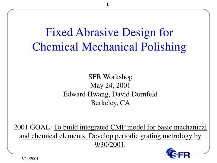
Fixed Abrasive Design for Chemical Mechanical Polishing. SFR Workshop May 24, 2001 Edward Hwang, David Dornfeld Berkeley, CA. 2001 GOAL: To b uild integrated CMP model for basic mechanical and chemical elements . Develop periodic grating metrology by 9/30/2001. Content.

E N D
Fixed Abrasive Design for Chemical Mechanical Polishing SFR Workshop May 24, 2001 Edward Hwang, David Dornfeld Berkeley, CA 2001 GOAL: To build integrated CMP model for basic mechanical and chemical elements. Develop periodic grating metrology by 9/30/2001.
Content • Micro-Fabrication Techniques for Fixed Abrasive for Chemical Mechanical Polishing (CMP) • Control of Abrasive Shape • Construction of Micro-Scale Wear Mode Diagram
Background Study & Examples Fixed Abrasive – Cylindrical Shape Pad Conditioner – Random geometry Abrasive shape decides the wear mode
Thermal Oxidation PR Uniform Pattern of Oxide Islands Oxide Si Silicon Etching Oxide Si Standard Fabrication Process Silicon Etching Process Determines Abrasive Shape
Planar Oxidation Non-Planar Oxidation Oxidation Sharpening limitations of various abrasive shape with the etching process due to crystallographic structure of silicon Anomaly of Silicon Oxidation at Regions of High Curvature due to Stress Configuration HF Etching Low Cost
Simulations with TSUPREM Wet etching + 6 consecutive wet + 4 consecutive dry oxidations at 950 C for 2 ½ hour Dry etching + 6 consecutive dry oxidations at 950 C for 2 ½ hour Isotropic etching + 6 consecutive dry oxidations at 950 C for 2 ½ hour 2-step wet etching + 4 consecutive wet + 4 Consecutive dry oxidations at 950 C for 2 ½ hour
Wet Etching + Oxidation Dry Etching + Oxidation Scanned Images Oxidation process sharpens the abrasive and sharpened image depends on the precursor
Additive Process • Abrasive Shape silicon oxide thickness, the opening deposited material silicon dioxide silicon substrate Lift-Off Technique
Third axis parameters to be determined 2002 and 2003 Goals Pin-on-disk set-up will be used to complete wear mode diagram Integrate initial chemical models into basic CMP model. Validate predicted pattern development by 9/30/2002. Develop comprehensive chemical and mechanical model. Perform experimental and metrological validation by 9/30/2003.