Download
1 / 1
10 likes | 237 Vues
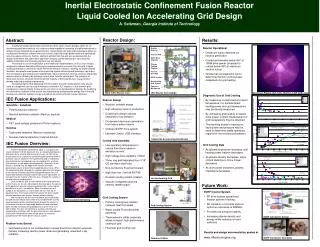
Inertial Electrostatic Confinement Fusion Reactor Liquid Cooled Ion Accelerating Grid Design A. Seltzman, University of Wisconsin - Madison. Abstract:. Reactor Design:. Results:.

E N D
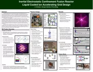
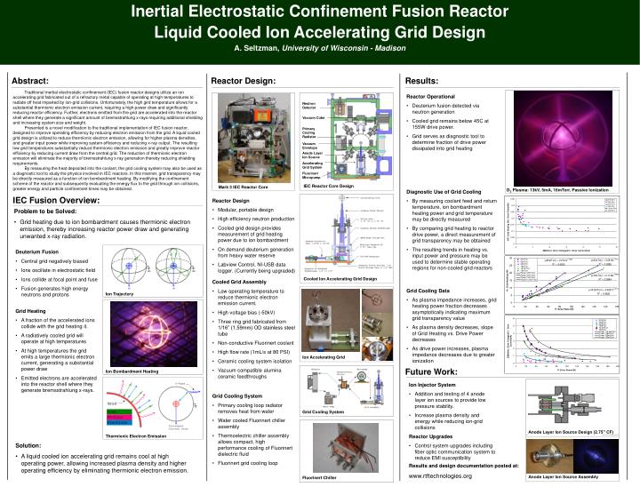
Inertial Electrostatic Confinement Fusion Reactor Liquid Cooled Ion Accelerating Grid Design A. Seltzman, University of Wisconsin - Madison Abstract: Reactor Design: Results: Traditional inertial electrostatic confinement (IEC) fusion reactor designs utilize an ion accelerating grid fabricated out of a refractory metal capable of operating at high temperatures to radiate off heat imparted by ion-grid collisions. Unfortunately, the high gird temperature allows for a substantial thermionic electron emission current, requiring a high power draw and significantly reducing reactor efficiency. Further, electrons emitted from the grid are accelerated into the reactor shell where they generate a significant amount of bremsstrahlung x-rays requiring additional shielding and increasing system size and weight. Presented is a novel modification to the traditional implementation of IEC fusion reactor, designed to improve operating efficiency by reducing electron emission from the grid. A liquid cooled grid design is utilized to reduce thermionic electron emission, allowing for higher plasma densities, and greater input power while improving system efficiency and reducing x-ray output. The resulting low grid temperatures substantially reduce thermionic electron emission and greatly improve reactor efficiency by reducing current draw from the central grid. The reduction of thermionic electron emission will eliminate the majority of bremsstrahlung x-ray generation thereby reducing shielding requirements. By measuring the heat deposited into the coolant, the grid cooling system may also be used as a diagnostic tool to study the physics involved in IEC reactors. In this manner, grid transparency may be directly measured as a function of ion bombardment heating. By modifying the confinement scheme of the reactor and subsequently evaluating the energy flux to the grid through ion collisions, greater energy and particle confinement times may be obtained. • Reactor Operational • Deuterium fusion detected via neutron generation • Cooled grid remains below 45C at 155W drive power. • Grid serves as diagnostic tool to determine fraction of drive power dissipated into grid heating Neutron Detector Vacuum Cube Primary Cooling Radiator Vacuum Envelope Anode Layer Ion Source Accelerating Grid System Fluorinert Micropump IEC Reactor Core Design Mark 3 IEC Reactor Core D2 Plasma: 13kV, 5mA, 16mTorr, Passive Ionization • Diagnostic Use of Grid Cooling • By measuring coolant feed and return temperature, ion bombardment heating power and grid temperature may be directly measured • By comparing grid heating to reactor drive power, a direct measurement of grid transparency may be obtained • The resulting trends in heating vs. input power and pressure may be used to determine stable operating regions for non-cooled grid reactors IEC Fusion Overview: • Reactor Design • Modular, portable design • High efficiency neutron production • Cooled grid design provides measurement of grid heating power due to ion bombardment • On demand deuterium generation from heavy water reserve • Labview Control, NI-USB data logger. (Currently being upgraded) • Problem to be Solved: • Grid heating due to ion bombardment causes thermionic electron emission, thereby increasing reactor power draw and generating unwanted x-ray radiation. • Deuterium Fusion • Central grid negatively biased • Ions oscillate in electrostatic field • Ions collide at focal point and fuse • Fusion generates high energy neutrons and protons Cooled Ion Accelerating Grid Design • Cooled Grid Assembly • Low operating temperature to reduce thermionic electron emission current. • High voltage bias (-50kV) • Three ring grid fabricated from 1/16” (1.59mm) OD stainless steel tube • Non-conductive Fluorinert coolant • High flow rate (1mL/s at 80 PSI) • Ceramic cooling system isolation • Vacuum compatible alumina ceramic feedthroughs • Grid Cooling Data • As plasma impedance increases, grid heating power fraction decreases asymptotically indicating maximum grid transparency value • As plasma density decreases, slope of Grid Heating vs. Drive Power decreases • As drive power increases, plasma impedance decreases due to greater ionization Ion Trajectory • Grid Heating • A fraction of the accelerated ions collide with the grid heating it. • A radiatively cooled grid will operate at high temperatures • At high temperatures the grid emits a large thermionic electron current, generating a substantial power draw • Emitted electrons are accelerated into the reactor shell where they generate bremsstrahlung x-rays. Ion Accelerating Grid Future Work: Ion Bombardment Heating • Ion Injector System • Addition and testing of 4 anode layer ion sources to provide low pressure stability. • Increase plasma density and energy while reducing ion-grid collisions • Reactor Upgrades • Control system upgrades including fiber optic communication system to reduce EMI susceptibility • Grid Cooling System • Primary cooling loop radiator removes heat from water • Water cooled Fluorinert chiller assembly • Thermoelectric chiller assembly allows compact, high performance cooling of Fluorinert dielectric fluid • Fluorinert grid cooling loop Grid Cooling System Anode Layer Ion Source Design (2.75” CF) Thermionic Electron Emission • Solution: • A liquid cooled ion accelerating grid remains cool at high operating power, allowing increased plasma density and higher operating efficiency by eliminating thermionic electron emission. Results and design documentation posted at: www.rtftechnologies.org Anode Layer Ion SourceAssembly Fluorinert Chiller