Download
1 / 31
310 likes | 470 Vues
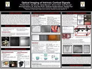
Dinesh Ganotra. Frequency analysis of optical imaging system. Imaging System. Lens Design Software. Effective Focal Length Max. Field Angle Stop Surface Number Afocal EFL Back Focal Length Zoom Surface Working Distance Wavelength (Primary) No. of Zoom Positions

E N D
Dinesh Ganotra Frequency analysis of optical imaging system
Lens Design Software • Effective Focal Length • Max. Field Angle • Stop Surface Number • Afocal EFL • Back Focal Length • Zoom Surface • Working Distance • Wavelength (Primary) • No. of Zoom Positions • Telephoto Ratio • Refractive Index (Primary) • Overall Physical Length • Abbe Number • Entrance Pupil Diameter • No. of Glass Elements • Max. Parax Image Height • Overall Glass Length • Lateral Magnification • No. of Optical Surfaces • Angular Magnification • No. of Physical Surfaces • Zoom Ratio • No. of Cemented Groups • Numerical Aperture • Number of Examples
Imaging system v u zo zi
Geometrical optics Diffraction optics : image amplitude : amplitude at image coordinates in response to a point source object at Amplitude point spread function
Amplitude Point Spread Function : Pupil function : unity inside and zero outside the projection aperture. Superposition integral
MTF PSF
Reduced coordinates ; Ideal image
Diffraction limited system • regard the image as being a convolution of the image predicted by geometrical optics with an impulse response that is the Fraunhofer diffraction pattern of the exit pupil.
Spatial coherence where is the time delay associated with propagation from to in general , is a function of the coordinates involved.
Drop time delays where known as mutual intensity.
Take time-varying phasor at the origin as reference For a perfectly coherent illumination Thus
Frequency response • Coherent illumination • Incoherent illumination
Coherent illumination • Define Amplitudetransferfunction Fourier transform of PSF
Coherent imaging … Taking Fourier transform on both the sides and using convolution theorem
Substituting h(u,v) Take and ignore negative signs
Cut off frequency Example = 10-4 cm w=1 cm zi = 10cm give cut off frequency of 100 cycles / mm
Incoherent illumination Convolution of intensity impulse response with ideal image intensity
Take FT on both sides and use convolution theorem Optical transfer function
Relationship between OTF and amplitude transfer function Amplitude Transfer Function Point Spread Function Optical Transfer Function OTF is normalized autocorrelation function of amplitude transfer function