Download
1 / 30
320 likes | 915 Vues
Design and Working Drawings. Working Drawings. Working Drawings. General:

E N D
Design and Working Drawings Working Drawings
Working Drawings General: Mechanical drafting principles are based on time tested practices based on standards set forth by The American Standards Institute (ANSI). Mechanical drawing techniques refers to a style or quality of a drawing imparted by the individual drafter to the work. It is characterized by crisp black line work, lettering, consistency, and uniformity. Mechanical drawings should reflect the rigid line control of a mechanically produced drawing. The development of good detail drawings is a real engineering accomplishment and art. Students should develop a stylized drawing technique that conforms to the rigid conventions of line drafting with added variations of artistic techniques to produce a very individualized finished drawing.
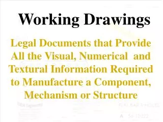
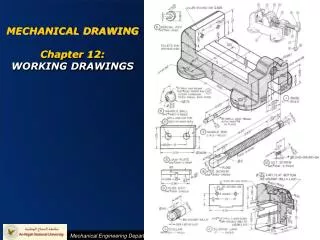
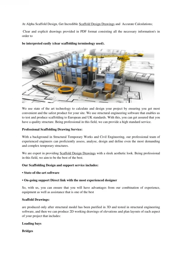
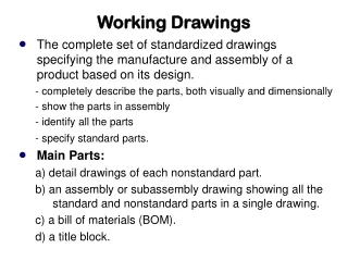
Working Drawings General: Working drawings or production drawings are a complete set of drawings used to bring the designed project to its finished state of manufacture. Working drawings usually consist of detail drawings and assembly drawings. Through the detail drawings the draftsman must convey in a technical language all information required to bring about the manufacture of each individual part. Assembly drawings show how all the parts go together in the complete product.
Working Drawings Selection of Views: A drawing should only contain those views needed for a clear and complete shape description of the object. Views are selected that show best the essential contours or shapes and contain the least number of hidden lines. Detail drawings and assembly drawings can utilize any number of necessary views including section views, auxiliary views, and partial views. The purpose of an assembly drawing is to show how the parts fit together and to suggest function. Therefore the views selected to show an assembly should convey the relationships of parts not show detailed shapes.
Working Drawings Number of Details per sheet: When several details are drawn on one sheet careful consideration must be given to spacing. The first step is to determine the necessary views for each detail. The second step is to arrange the views to allow ample space for dimensions and notes. Views from one detail should not overlap views from another. The same scale should be used for all details on a single sheet.
Working Drawings Drawing Numbers: All drawings will be numbered. There are many different numbering systems used throughout industry so that there is no one standard system used. Numbering will depend on the company standards and drafting practice. Drawing numbers are very important and therefore are lettered with large letters. The heights range from 3/8" to 5/16" high.
Working Drawings Parts List: The Parts List is a listing of all of the component parts of the assembly. The Parts List includes part number, part name, number required, material of part, and sometimes other descriptive text. The Parts List is included on all detail drawings and assembly drawings or can be on a separate sheet. Generally the parts list is shown with the assembly drawings and includes only those parts shown on the assembly drawing sheet.
Working Drawings Revision Blocks: Revision blocks always appear on a drawing to record any changes that are made after the drawing has been approved. Changes to the drawing are necessitated by changes in design, changes made by the customer, or changes due to errors in design. Changes should be noted on the drawing and recorded in the revision block. A brief description of the change should be noted along with the date and the initials of the person making the change.
Working Drawings General Assemblies: The purpose of an assembly drawing is to show how the parts fit together and to suggest function. Therefore the views selected to show an assembly should convey the relationships of parts not show detailed shapes.
Working Drawings Section views: Sectioning is used extensively in assembly drawings to eliminate the need to draw hidden parts. Any kind section view such as full sections, half sections, aligned sections, offset sections may be used. To distinguish between adjacent parts in a section view section lines are drawn in opposing directions. Section lining may also vary in spacing to distinguish between adjacent parts. For general use, the cast-iron general-purpose sectioning lining is used. Thin parts in assembly drawings should be solid black instead of using section lining. Rounded parts such as bolts, shafts, pins, keys, nuts, etc. are not crosshatched even though the cutting plane passes through them. It is customary to show these parts unsectioned or "in the round."
Working Drawings Hidden lines: Views should be chosen that show as many features with visible lines as possible. Hidden lines should be used wherever necessary to make the drawing clear. Where they are not needed for clearness they should be omitted. Hidden lines in assembly drawings are generally not needed as a result of extensive use of section views. They should be used wherever necessary for clearness.
Working Drawings Dimensions: Dimensions are included on all detail drawings. All of the rules and techniques of dimensioning as specified by ANSI apply. Dimensioning can be either unidirectional or aligned but not both in the same set of drawings. Dimensions are not generally given on assembly drawings. If dimensions are included, they are limited to some function of the object as a whole. These would include showing a minimum or a maximum dimension, a dimension that is needed when machining is required in the assembly process, or general notes applied to the overall assembly.
Working Drawings Center Lines: Center lines are used to indicate an axis of symmetry, show paths of motion, or used as extension lines in dimensioning. Center lines are used mainly in dimensioning and should be omitted from unimportant shapes. Center lines should be used in assembly drawings to show symmetry between mating parts, alignment of parts, and paths of motion to suggest function.
Working Drawings Part Identification: Circles containing part numbers are used to identify parts on detail and assembly drawings. Identification circles are 7/16” to 1/2” diameter as shown. Identification circles on assembly drawings are placed adjacent to the parts with leaders terminated by arrowheads touching the parts. Identification circles used to identify a detail drawing of a part are placed below the detail.
Working Drawings Part Identification: Identification circles on assembly drawings are placed adjacent to the parts with leaders terminated by arrowheads touching the parts. Leader lines can vary in style such as leaders with shoulders, without shoulders, straight line leaders or leaders that are curved. Curved leader lines are drawn using the SPLINE setting. Leader terminators can be either arrowheads touching the part or dots extended to the inside of the part.
Working Drawings Titles: All entities on a drawing must have a title whether it is an assembly, section view, detail, note column, symbols legend, etc. Titles are lettered large enough catch the viewer’s eye. Generally the lettering is between 1/4" and 3/4" high. To accent the titles even more they can underlined. Underlining can consist of a single line, a double line, or a combination of thick and thin lines. The underlining can be centered with the lettering, be flush, or be broken when using circle call-outs.
Working Drawings Lettering: Lettering heights will be in accordance with the recommendations of the ANSI Standards. General lettering and dimensioning uses 3/32" to 1/8" high lettering with 1/8" being the preferred size.
Working Drawings Drawing Scales: The standard unit of mechanical measurement is either Inches or Millimeters. The scale is always noted as INCHES such as 1" = 1" or 1/2" = 1", or as MILLIMETERS such as 1mm = 1mm. The word SCALE is always written to identify what is being read for example SCALE: 1" = 1". When a drawing sheet contains details drawn using different scales the notation SCALE: AS NOTED is used in the title block. When a detail or drawing is not made to any scale the notation N.T.S. is used to indicate that the drawing is NOT TO SCALE.
Working Drawings Title Blocks: Title blocks are a very important part of the overall drawing. They contain information not given directly on the drawing with dimensions or notes. Title blocks for structural drawings are prepared according to the specifications set forth by the company. The following information is generally provided in the title block: Title of the project/name of the drawing Name and address of the client. Name and address of the manufacturing company. Date of the completion of the drawing package. Scale of the drawing. Drawing Number. Lettering should be simple and conform to the overall lettering style of the drawing. All lettering should be upper case letters.
Working Drawings Title Blocks: The heights of the lettering should follow in accordance with their relative importance. The drawing number should receive the greatest emphasis and have a height greater than 1/4". The drawing name, title of the project, client’s name, and the name of the company should follow with a letter height of 3/16". The addresses, the date, and the scale should have a letter height of 1/8". Incidental words like DATE and SCALE should receive the least emphasis and have a letter height of 1/16". The lettering in the title block should be either centered or have a flush margin. Variations in the lettering heights adds an overall pleasing affect to the drawing and breaks up the monotony of a line drawing and the margins tie in with overall style of the drawing adding continuity and consistency to the drawing.
Working Drawings General Notes: Notes are classified as general notes and as local notes. Notes are lettered horizontally on a sheet and arranged in a systematic manner. Abbreviations in general notes should be avoided as much as possible. Proper grammar, sentence structure and punctuation are used in constructing a note. All lettering is upper case letters.
Working Drawings General Notes: Note columns are titled to make them distinguishable from other parts of the drawing. The lettering heights for titles are larger than the lettering height use for general lettering and should be the same height as other titles on the sheet. Each note in a note column is referenced with a number. Margins are used to align the note numbers and the notes. The spacing between lines in a note should single spaced. Spacing between notes should double spaced so that each note is distinguished from the other notes. Remember, uniformity and consistency plays an important role in the construction of the note column.
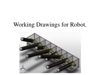
Working Drawings A set of working drawings includes the detail drawing of the individual parts and the assembly drawing of the assembled unit. An assembly drawing shows the assembled machine or structure with all detail parts in their functional positions. Assembly drawings show how the parts fit together in the assembly and to suggest function. Assembly drawings show relationships of parts, not detailed shapes so the views selected should be the minimum view needed to show how the parts fit together.
Working Drawings Section Views in Assembly Drawings: Sectioning is used extensively in assembly drawings to eliminate the need to draw hidden parts. Any kind of section view such as full sections, half sections, aligned sections, and offset sections may be used.
Working Drawings Assembly Sectioning: To distinguish between adjacent parts in an assembly section drawing section lines are drawn in opposite directions (figure b). The first large area (figure a) is sectioned lined at 45 degrees. The next large area is section lined at 45 degrees in the opposite direction (figure b). Smaller areas are then section lined using other angles such as 30 degrees or 60 degrees as shown in figure (c). In small areas if may be necessary to space the section lines closer together (figure c).
Working Drawings Assembly Sectioning: For general use, the cast-iron general purpose section lining is used for assemblies. Whenever it is necessary to give a general indication of the materials used, the symbolic section lining may be used.
Working Drawings Assembly sectioning: In sectioning thin parts in an assembly such as gaskets conventional section lining is ineffective. Thin parts should be shown in solid black instead of using conventional section lining.
Working Drawings Sheet Layout: The drawing paper needs to be framed with a border line. The Title block, Parts List, and Revision Block are added and placed along the bottom and/or the right side of the border. In general, all of the drawing area should be filled. The main drawing should be the dominate picture on the sheet with detail drawings and general notes related to the main drawing placed around it. Assembly views and detail drawings can be combined on one sheet or details shown together and assemblies shown on separate sheets. The drafter should determine the necessary views for each assembly and detail. Ample space should be allowed for all dimensioning and notes. Views from one detail should not overlap views from another.
Working Drawings Sheet Layout: All drawings, details, and notes should be titled. Titles are placed beneath the picture. Sheet Layout
Working Drawings Installation Assembly: