Download

1 / 33
330 likes | 342 Vues
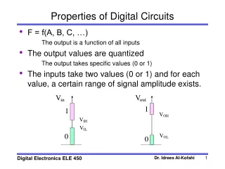
Digital Circuits. Review – Getting the truth table. The first step in designing a digital circuit usually is to get the truth table. That is, for every input combination, figure out what an output bit should be, and write them down in a table. Review – From the truth table to circuits.

E N D
Review – Getting the truth table • The first step in designing a digital circuit usually is to get the truth table. • That is, for every input combination, figure out what an output bit should be, and write them down in a table.
Review – From the truth table to circuits • Any truth table can be translated into a circuits consisting of several and gates followed by one or gate. • It means that any function can be implemented in this way • Call a row in the truth table in which the output is `1’ a ``true row’’ and the input combination in this row a ``true input combination’’ or just a ``true combination.’’ • Each and gate corresponds to one ``true row’’ in the truth table. The and gate should output a `1’ if and only if the input combination is the same as this row. If all other cases, the output of this and gate is `0.’ • So, whenever the input combination is the same as one of the ``true combinations,’’ one of the and gates outputs ``1’’, so the output of the or gate is 1. • If the input combination is not the same as any of the ``true combinations,’’ none of the and gates will output a ``1’’, so the output of the or gate is 0.
Logic Functions • Drawing circuits is … Usually we express logic functions using logic equations which are more succinct and carry the same information • The OR operator is written as +, as in A + B. • The AND operator is written as ·, as A · B. • The unary operator NOT is written as or A’. • Remember: This is NOT the binary field. Here 0+0=0, 0+1=1+0=1, 1+1=1.
Logic functions • For example, the sum in the one-bit full adder is • From a logic function you can immediately know what the circuit looks like. • Truth table == Circuits == Logic function, equivalent. • So we are going to get familiar with getting the logic functions from the truth table
Problems • Ex 1. Assume that X consists of 3 bits, x2 x1 x0. Write a logic function that is true if and only if X contains only one 0
Ex 1 • Output = x2x1x0’ + x2x1’x0 + x2’x1x0
Ex 2 • Assume that X consists of 3 bits, x2 x1 x0. Write a logic functions that is true if and only if X contains an even number of 0s.
Ex 2 • Output = x2x1’x0’ + x2’x1’x0 + x2’x1x0’+ x2x1x0
Ex 3 • Assume that X consists of 3 bits, x2 x1 x0. Write a logic functions that is true if and only if X when interpreted as an unsigned binary number is no less than 5.
Ex 3 • Output = x2x1’x0 + x2x1x0’+ x2x1x0
In class exercises 1 • Assume that X consists of 3 bits, x2 x1 x0. Write a logic functions that is true if and only if X when interpreted as an unsigned binary number is less than 4.
In class exercises 2 • Implement a circuit with three inputs (X2, X1, X0), and one output O. O should be 1 only when X2, X1, X0 are representing an odd binary number.
Simplifying Digital Circuits • Reconsider the 1-bit full adder. The carry bit is • But we can implement the function with a much simpler circuit: • How to get there?
Simplifying digital circuit • There are many methods. • Using boolean algebra • Using K-map • By just being really smart…
Boolean Algebra Laws A+A=A, A*A=A
Boolean Algebra • To use Boolean algebra, note that CO= abc’+ab’c+a’bc+abc • Now, • abc’+abc=ab(c’+c)=ab. • ab’c+abc=ac(b’+b)=ac • a’bc+abc=bc(a’+a)=bc • We used term abc three times because abc=abc+abc+abc!
K-map • It is actually more convenient to use K-map to simplify digital circuits. • K-map is a very mechanical procedure. Nothing fancy. • It basically uses two rules: A+A=A, and AB+AB’=A.
K-map • K-map • CO = ab + ac + bc ab c 00 01 10 11 0 1
K-map rules • Draw the K-map. Remember to make sure that the adjacent rows/columns differ by only one bit. • According to the truth table, write 1 in the boxes. • Draw a circle around a rectangle with all 1s. The rectangle must have size 1,2,4,8,16…Then, reduce the terms by writing down the variables whose values do not change. • For example, if there is a rectangle with two 1s representing ab’c’ and ab’c, you write a term as ab’. • A term may be covered in multiple circles. • The rectangle can wrap-around! • Simplify to the simplest circuits possible: • The circle should be as large as possible. • Try to get the minimum number of circles, i.e., minimum number of terms in the equation.
K-map • F=a’bc’+a’bc+a’b’c+ab’c ab c 00 01 10 11 0 1
K-map • F=a’bc’+a’bc+a’b’c+ab’c • F=a’b+b’c ab c 00 01 10 11 0 1
K-map • F=a’bc’+a’bc+abc’+abc+a’b’c ab c 00 01 10 11 0 1
K-map • F=a’bc’+a’bc+abc’+abc+a’b’c • F=b+a’c ab c 00 01 10 11 0 1
K-map • F=a’bc’d+a’bcd+abc’d+abcd+a’b’c’d+abcd’ ab cd 00 01 10 11 00 01 11 10
K-map • F=a’bc’d+a’bcd+abc’d+abcd+a’b’c’d+abcd’ • F=bd+a’c’d+abc ab cd 00 01 10 11 00 01 11 10