Download
1 / 19
200 likes | 213 Vues
Television. Reference Books: Monochrome and Color Television By R R Gulati Basic Television- Principles and servicing By Bernard Grob. Television. Contents Introduction Application Elements of a Television System Television Broadcasting channels. Introduction.

E N D
Television Reference Books: Monochrome and Color Television By R R Gulati Basic Television- Principles and servicing By Bernard Grob
Television • Contents • Introduction • Application • Elements of a Television System • Television Broadcasting channels
Introduction • Development of Television • Application of Television • Equipment • Coverage • Recent Trends
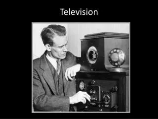
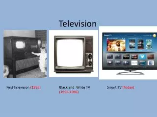
Development of Television • Television means “to see from a distance” • The first demonstration of actual television was given by J. L. Baird in UK and C.F. Jenkins in USA around 1927 using the technique of mechanical scanning using rotating discs • Real breakthrough occurred with the invention of Cathode Ray Tube (CRT) and first camera tube based on storage principle (V.K. Zworykin of USA) • By 1930 electromagnetic scanning of both CRT and camera were developed with other ancillary circuits: beam deflection, video amplification, etc. • Television broadcast was started in 1935 but its progress was slowed down due to Second World War
Television System • Initially due to the absence of any international standard three monochrome systems: 525 line American, 625 line European, and 819 line French grew independently. • Later initiatives have been taken for establishing a common 625 line system. However, due to huge involvement to change equipment and millions of Rx already in use for all the three systems. • Three different standards of monochrome television have resulted in the development of three different systems color television. • In 1953 USA adopted on the recommendation of its National Television Systems Committee and hence called NTSC system. • The other two color systems: PAL (Phase Alternating Line) and SECAM (SéquentielCouleurà Mémoire)are later modifications of the NTSC system to confirm the other two monochrome standards. • Regular color transmission started in USA in 1954. • In 1960 Japan adopted NTSC system followed by Canada and other several countries
Television System • The PAL color system compatible with 625 line monochrome system developed by Telefunken Laboratory of Federal Republic of Germany (FRG). • PAL system reduces the color display errors that occurred in NTSC system. • PAL system adopted by FRG and UK in 1967, and subsequently Australia, Spain, Iran, India, Bangladesh, and several other west and south Asia countries. • The third color system in use is the SECAM system. This was initially developed and adopted in France in 1967. Later versions known as SECAM IV and SECAM V were developed in Russian National Institute of Research (NIR) and sometimes referred to as NIR-SECAM system. • This system adopted by USSR, Germany Democratic Republic, Hungary, some other East European countries, Algeria. • The adaptation of a particular color system depends on the monochrome system of the respective countries
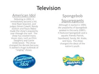
Application of Television • Impact of television is far and wide, and has opened new avenues in diverse fields like • public entertainment, Newscasts and weather reports, • political organization and campaigns, • announcements and guidance at public places like airport • terminals, sales promotion and many others. • Closed Circuit Television (CCTV) is a special application • Group demonstrations of surgical operations or scientific experiments, inspection of noxious or dangerous industrial or scientific processes (e.g. nuclear fuel processing) or of underwater operations and surveillance of areas for security purposes are some typical examples. • A special type of CCTV is what might be called wired community TV. • Another potential use of CCTV that can become popular and is already technically feasible is a video-telephone or ‘visiphone’.
Equipment • Television broadcasting requires • Extensive lighting facilities, cameras, microphones, and control equipment for television studios. • Transmitting equipment for modulation, amplification and radiation of the signals at the high frequencies. • A wide variety of support equipment essential in broadcast studios and control rooms. • Besides the above video tape recorders, telecine machines, special effects equipment plus all the apparatus for high quality sound broadcast.
Coverage • Microwave based relay station. A matrix of such relay stations can be used to provide complete national coverage. • VHF bands of 41 to 68 Mhz and 174 to 230 MHz. and UHF band between 470 and 890 MHz. This usually varies between 75 and 140 km depending on the topography and radiated power. • Global coverage by linking national TV systems through satellites. Area of TV broadcast coverage can be extended further by coaxial cables. • Another method is to employ somewhat higher transmitter power on the satellite and receive the down transmissions directly through larger dish antenna on conventional television receivers fitted with an extra front-end converter.
Recent Trends • Conventional TV broadcasting technologies have been replaced by solid state technology • Digital TV broadcasting • Development of advanced display technology
What a Television Broadcasting Is? • Picture transmission • Sound transmission • Picture reception • Sound reception • Synchronization
Monochrome Television Receiver The receiver is of the heterodyne type and employs two or three stages of intermediate frequency (IF) amplification. The output from the last IF stage is demodulated to recover the video signal.
Picture Reception The signal that carries the picture information is amplified and coupled to the picture tube which converts the electrical signal back into picture elements of the same degree of black and white.
Picture Reception • The picture tube is very similar to the CRT used in an oscilloscope. • The glass envelope contains an electron gun structure that produces a beam of electrons aimed at the fluorescent screen. • When the electron beam strikes the screen, light is emitted. • The beam is deflected by a pair of deflecting coils mounted on the neck of the picture tube in the same way and rate as the beam scans the target in the camera tube. • The amplitudes of the currents in the horizontal and vertical deflecting coils are so adjusted that the entire screen, called raster, gets illuminated because of the fast rate of scanning.
Picture Reception (contd.) • The video signal is fed to the grid or cathode of the picture tube. When the varying signal voltage makes the control grid less negative, the beam current is increased, making the spot of light on the screen brighter. • More negative grid voltage reduces the brightness. If the grid voltages is negative enough to cut-off the electron beam current at the picture tube there will be no light. This state corresponds to black. • Thus the video signal illuminates the fluorescent screen from white to black through various shades of grey depending on its amplitude at any instant. • This corresponds to the brightness changes encountered by the electron beam of the camera tube while scanning the picture details element by element. • The rate at which the spot of light moves is so fast that the eye is unable to follow it and so a complete picture is seen because of the storage capability of the human eye.
Sound Reception • The path of the sound signal is common with the picture signal from antenna to the video detector section of the receiver. • Here the two signals are separated and fed to their respective channels. • The frequency modulated audio signal is demodulated after at least one stage of amplification. • The audio output from the FM detector is given due amplification before feeding it to the loudspeaker.
Synchronization • To ensure perfect synchronization between the scene being televised and the picture produced on the raster, synchronizing pulses are transmitted during the retrace. (i.e., fly-back intervals of horizontal and vertical motions of the camera scanning beam.) • In addition to carrying picture detail, the radiated signal at the transmitter also contains synchronizing pulses. • These pulses which are distinct for horizontal and vertical motion control, are processed at the receiver • And fed to the picture tube sweep circuitry thus ensuring that the receiver picture tube beam is in step with the transmitter camera tube beam.
Television Broadcast Channels The band of frequencies assigned for transmission of the and sound signals is a television channel. FCC assigned 6 MHz for a channel