Download
1 / 31
320 likes | 430 Vues
AMS-02 Delta CDR. Thermal. Overview. Changing from Cryomagnet to PM greatly simplifies AMS-02 Thermal requirements Keeping vacuum Case “cold as possible” is no longer necessary. Analysis cases are also reduced: Magnet charging Magnet discharging Varying Cryocooler power.

E N D
AMS-02 Delta CDR Thermal
Overview • Changing from Cryomagnet to PM greatly simplifies AMS-02 Thermal requirements • Keeping vacuum Case “cold as possible” is no longer necessary. • Analysis cases are also reduced: • Magnet charging • Magnet discharging • Varying Cryocooler power
Overview (cont.) Silver-Teflon surface area is greatly reduced (Zenith radiators, CAB, VC). New Tracker Plane 1 (above TRD) will require additional MLI and heaters. Tracker Plane 6 mod (between RICH and ECAL) requires rerouting of TTCS tubing, but TTCS system remains functionally similar (same heat load, etc).
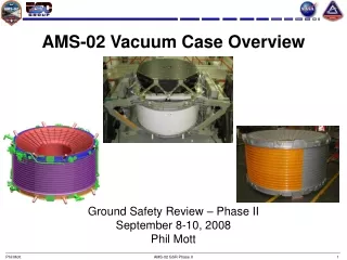
Permanent Magnet (PM) • The AMS-01 PM model has been integrated into the Vacuum Case (VC). • The Cryomagnet magnet was assume to have no affect on VC temperatures. • With the additional mass of the PM in the model, VC temperatures are expected to be moderated.
New PM w/Support Structure Permanent Magnet Double X structure
Vacuum Case Optics • The STA VC used to house the PM will not have silver-Teflon on the +/- X surfaces. This will now be clear anodized aluminum. • This will cause VC temperature to be slightly higher in average, but will reduce specular reflections to ISS and adjacent payload site.
VC Optics Silver-Teflon
VC Optics Clear Anodized Aluminum
Zenith Radiators and Cryocooler LHPs • The silver-Teflon radiators will be replaced with a Betacloth MLI blanket. • Reduced specular surface area and a reduction of heat generation (400-600W). • Since these surfaces are pointing zenith, there should be little influence on ISS or adjacent payloads.
Zenith Radiators Silver-Teflon
Zenith Radiators Betacloth
Cryocoolers and CCEB • Removing cryocoolers from VC Support Rings is a minor geometry change that should have little affect on anything. • Boards will be removed from CCEB. This will reduce heat load on Main Radiators
Cryocoolers Crycoolers (x4)
CAB and CAB LHP • Removing the CAB will change external geometry and remove a source of power (60W, TBC) • Removing CAB LHP will slightly reduce heat load on Wake Main Radiator.
Dump Diodes The Dump Diodes will be removed from the -X+Y Sill Trunnion Joint This a minor geometry change
UPS’s The UPS’s will be removed A minor geometry change
Cryo Support Hardware Dump Diodes UPS CAB
Cryo Support Hardware Dump Diodes UPS
New Tracker Plane 1N Modeling and analysis is being performed by Carlo Gavazzi Space. TTCS will not be used to cool Tracker hybrids. Plane 1N will be enclosed in MLI (new). Heaters will be used to maintain Tracker within limits.
MLI CFRP Al HC HEATER PATCH CFRP HYBRIDS TRACKER PLANE IF bracket (X8) COPPER BRAID MLI TRD upper h/c plane THERMAL MODELLING
Tracker Plane 1N Thermal Preliminary results indicate 160W of heaters can maintain Tracker P1N with limits in the coldest ISS environment. Some heat may be required even in hot cases Detailed implementation and control methods are still in work. Thermal impacts to TRD are also in work.
Tracker Plane 6 Thermal Tracker Plane 6 will be relocated between the RICH and the ECAL Cooling will be performed by TTCS system as before. Tubing will have to be rerouted, but TTCS performance should not be significantly impacted. Modifications to MLI are being evaluated.