Download
1 / 12
120 likes | 125 Vues
AMS-02 Vacuum Case Overview. Ground Safety Review – Phase II September 8-10, 2008 Phil Mott. Vacuum Case. CONICAL FLANGE 2X. UPPER SUPPORT RING. CLEVIS PLATE 2X. STRAP PORT 16X. INNER CYLINDER. UPPER INTERFACE PLATE 4X. OUTER CYLINDER. LOWER SUPPORT RING.

E N D
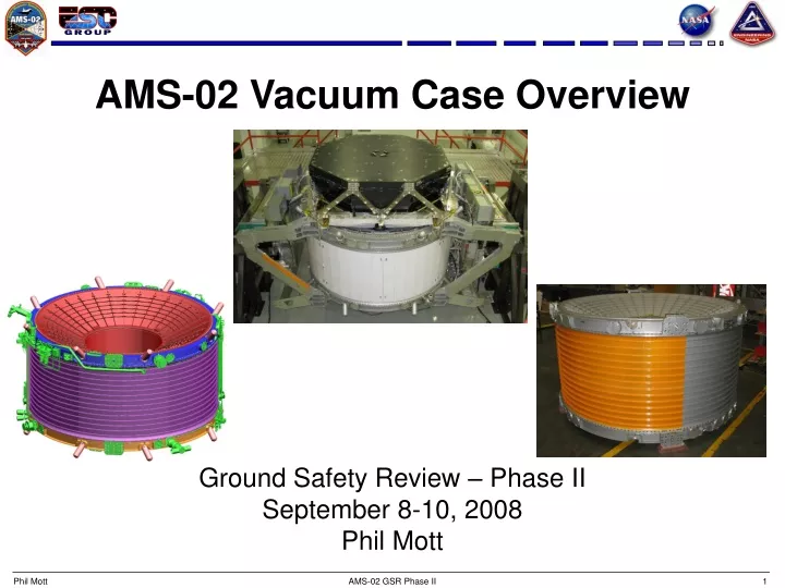
AMS-02 Vacuum Case Overview Ground Safety Review – Phase II September 8-10, 2008 Phil Mott AMS-02 GSR Phase II
Vacuum Case CONICAL FLANGE 2X UPPER SUPPORT RING CLEVIS PLATE 2X STRAP PORT 16X INNER CYLINDER UPPER INTERFACE PLATE 4X OUTER CYLINDER LOWER SUPPORT RING ELECTRICAL/PLUMBING/CRYOCOOLER PORT 25X LOWER INTERFACE PLATE 4X AMS-02 GSR Phase II
Vacuum Case with External Hardware Warm He Tank with MMOD Shield VC Burst Disc with Zero Thrust Vent SFHe Tank Burst Disc with Zero Thrust Vent AMS-02 GSR Phase II
SUPER INSULATION & VAPOR COOLED SHIELDS MAGNET RACETRACK COIL (DIPOLE COIL ROTATED 90o) SUPERFLUID HELIUM TANK VACUUM SPACE 1 x 10⁻⁶ TORR SUPER INSULATION & VAPOR COOLED SHIELDS OUTER JOINT UPPER CONICAL FLANGE UPPER SUPPORT RING INNER JOINT UPPER INTERFACE PLATE Vacuum Case Cross Section OUTER CYLINDER Skin thickness between each rib varies from .152” - .265” INNER CYLINDER LOWER INTERFACE PLATE LOWER CONICAL FLANGE LOWER SUPPORT RING AMS-02 GSR Phase II
Inner Joint UPPER or LOWER CONICAL FLANGE • Welded Joint – U Groove Design, 3 Pass. • O-Ring joint not possible due to design constraints on both sides of the joint. • Joint is designed for 3 welds – Initial plus 2 contingencies. • Three complete closeout welds will take place prior to the closeout weld on the Flight Assembly: • First Article (initial & 1 re-weld) • STA at vendor’s facility for pressure and leak tests. • STA at SCL in Culham, England. 5/16 WELD PREP MAGNET KEEP-IN ZONE INNER CYLINDER COMPLETED WELD AMS-02 GSR Phase II
INTERFACE PLATE O-RING TEST PORT SUPPORT RING CONICAL FLANGE VACUUM SPACE Outer Joint • Double O-Ring bolted joint. • Mechanical attachment: • Conical Flange, Upper: 232 .250-28UNJF • Outer Cylinder, Upper: 192 .250-28UNJF • Outer Cylinder, Lower: 168 .250-28UNJF & 32 .3125-24UNJF • Conical Flange, Lower: 192 .250-28UNJF • O-Ring material is Viton, 75 Durometer. • Test ports between each O-Ring for individual leak checks. HEX PLUG TO SEAL TEST PORT with O-Ring OUTER CYLINDER O-RINGS TYPICAL O-RING CONFIGURATION FOR SUPPORT RING TO OUTER CYLINDER AND SUPPORT RING TO CONICAL FLANGE AMS-02 GSR Phase II
Feedthru Ports & Cryocooler Ports • Mechanical Attachment • 8 .190-32UNJF • Double O-Ring joint • Viton, 75 Durometer • Test Port between O-Rings O-RING TEST PORT (HEX PLUG NOT SHOWN FOR CLARITY) ORIENTATION & LOCATION WILL VARY DEPENDING ON THE ATTACHED COMPONENT SUPPORT RING (UPPER OR LOWER) VACUUM CASE FEEDTHRU PORT O-RINGS MATING COMPONENT OUTER CYLINDER AMS-02 GSR Phase II
Strap Port STRAP ASSEMBLY • Closeout Cap Mechanical Attachment • 8 .190-32UNJF • Double O-Ring joint • Viton, 75 Durometer • Test Port between O-Rings STRAP CLOSEOUT CAP SUPPORT RING O-RINGS (TEST PORT NOT SHOWN IN THIS VIEW) AMS-02 GSR Phase II
Closeout Weld AMS-02 GSR Phase II
Closeout Weld Inspection • Joint design does not allow for x-ray inspection of the weld • Weld is visually and dye penetrant inspected. • Weld is ultrasonically inspected using a phased array system. The STA weld at the vendor was inspected manually. • Both methods have been qualified to MSFC-SPEC-504C using flat plates and a First Article. AMS-02 GSR Phase II
Vacuum Leak Test • Both the Flight and STA VC’s were vacuum tested at the vendor. Both met the vacuum requirement of 1 x 10⁻⁶ torr. • Each O-Ring was individually tested. • Helium leak rate for both VC’s met the spec of 1.0 x 10⁻⁷ std cc/sec AMS-02 GSR Phase II
Proof Pressure Test • The STA VC has been successfully proof pressure tested with argon at the vendor and at SM. • Proof pressure: 1.8 atm absolute (26.5 psi). [1.0 x MDP] AMS-02 GSR Phase II