Download
1 / 25
250 likes | 408 Vues
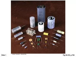
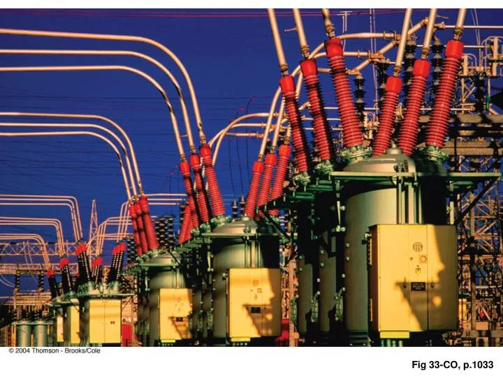
Fig 33-CO, p.1033. Ch 33 Alternating Current Circuits 33.1 AC Sources and Phasors v = V max sint = 2/T = 2f. V max. v = V max sint. t. Phasor.

E N D
Ch 33 Alternating Current Circuits 33.1 AC Sources and Phasors v = Vmaxsint = 2/T = 2f Vmax v = Vmaxsint t Phasor
CT1: The phasor diagrams below represent three oscillating voltages having different amplitudes and frequencies at a certain instant of time t = 0. As t increases, each phasor rotates counterclockwise and completely determines a sinusoidal oscillation. At the instant of time shown, the instantaneous value of v associated with each phasor is given in ascending order by diagrams • a,b,c. • a,c,b. • b,c,a. • b,a,c. • c,a,b • c,b,a
CT2: Consider the pairs of phasors below, each shown at t = 0. All are characterized by a common frequency of oscillation . If we add the oscillations, the maximum amplitude is achieved for pair(s) • a. • b. • c. • d. • e. • c and d. • a and c. • b and c.
Ch 33 Alternating Current Circuits 33.2 Resistors in an AC Circuit iR = vR/R = Vmaxsint/R = Imaxsint Imax = Vmax/R
Ch 33 Alternating Current Circuits 33.2 Resistors in an AC Circuit Irms = Imax/21/2 Vrms = Vmax/21/2 Pav = Prms = Irms2R = Vrms2/R Vrms = IrmsR P33.2 (p.946) P33.4 (p.946)
Ch 33 Alternating Current Circuits 33.3 Inductors in an AC Circuit vL = Vmaxsint Imax = Vmax/L iL = Imaxsin(t - /2) lags voltage by /2 P33.11 (p.946) XL = L Imax = Vmax/XL
Ch 33 Alternating Current Circuits 33.4 Capacitors in an AC Circuit vL = Vmaxsint Imax = CVmax iC = Imaxsin(t + /2) leads voltage by /2 P33.15 (p.946) XC = 1/C Imax = Vmax/XC
CT3: The light bulb has a resistance R, and the • emf drives the circuit with a frequency . • The light bulb glows most brightly at • very low frequencies. • very high frequencies. • the frequency = (1/LC)1/2
Ch 33 Alternating Current Circuits 33.5 RLC Series Circuit v = Vmaxsint Imax = Vmax/Z i= Imaxsin(t - ) I lags voltage by Z = (R2 + (XL – XC)2)1/2 = tan-1[(XL –XC)/R] i
P33.17 (p.946) P33.27 (p.947)
Ch 33 Alternating Current Circuits 33.6 Power in an AC Circuit Pav = Prms = IrmsVrmscos cos is called the power factor Check P33.27 (p.947) i
Ch 33 Alternating Current Circuits 33.7 Resonance in a Series RLC Circuit Pav = Vrms2R/(R2 + L2(2 - 02)2/2) 0 = (1/LC)1/2 Q = 0/ = R/L i
CT4: For the RLC series circuit shown, which of • these statements is/are true: • (i) Potential energy oscillates between C and L. • (ii) The source does no net work: Energy lost • in R is compensated by energy stored in C and L. • (iii) The current through C is 90° out of phase • with the current through L. • (iv) The current through C is 180° out of phase • with the current through L. • (v) All energy is dissipated in R. • all of them • none of them • (v) • (ii) • (i), (iv), and (v) • (i) and (v) • none of the above
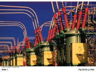
Ch 33 Alternating Current Circuits 33.8 The Transformer and Power Transmission V2 = N2V1/N1 Ideal Transformer: Ppri = I1V1 = Psec = I2V2 P33.41 (p.948) V2 i
CT5: When the switch is closed, the potential difference across R is • V(N2 /N1). • V(N1/N2). • V. • zero. • insufficient information
CT6: The primary coil of a transformer is connected to a battery, a resistor, and a switch. The secondary coil is connected to an ammeter. When the switch is thrown closed, the ammeter shows • zero current. • a nonzero current for a short instant. • a steady current.