Download
1 / 24
240 likes | 379 Vues
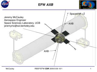
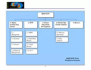
EFW Science Overview. Professor John R. Wygant (PI) University of Minnesota. +Z. EFW Instrument Overview. RBSP EFW Features Four spin plane booms (2 x 40 m and 2x 50 m) Two spin axis stacer booms (2x6 m) Spherical sensors and preamplifiers near outboard tip of boom (400 kHz response)

E N D
EFW Science Overview Professor John R. Wygant (PI) University of Minnesota EFW INST+SOC PDR
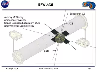
+Z EFW Instrument Overview • RBSP EFW Features • Four spin plane booms (2 x 40 m and 2x 50 m) • Two spin axis stacer booms (2x6 m) • Spherical sensors and preamplifiers near outboard tip of boom (400 kHz response) • Flexible boom cable to power sensor electronics & return signals back to SC • Sensors are current biased by instrument command to be within ~ 1 volt of ambient plasma potential. • Main electronic box (sensor bias control filtering, A-D conversion, burst memory, diagnostics, mode commanding, TM formatting ) • EFW Science quantities include: • • E-fields:(V1-V2, V3-V4, V5-V6) • Interferometric timing: SC-sensor potential (V1s, V2s, V3s, V4s, V5s, V6s) • SC Potential : (V1+V2)/2, (V3+V4)/2 • Interface to EMFISIS instrument • Electrostatic cleanliness spec: variations of potential across spacecraft surfaces smaller than 1 Volt. 2 5 4 3 6 Not to Scale 1 EFW INST+SOC PDR
Investigation Team RBSP Project Office APL RBSP SWG EFW PI John Wygant UMN EFW Co-I team EFW PM Keith Goetz UMN EFW CAM Kim Cooper APL LASP lead Bob Ergun LASP UCB lead John Bonnell UCB SE Dave Curtis UCB SMA Ron Jackson UCB Finance Kate Harps UCB LASP PM Mary Bolton LASP UCB PM John Bonnell UCB DFB Susan Batiste LASP Mechanical Paul Turin UCB Electrical Michael Ludlam UCB Flight Software Peter Harvey UCB Ground SW Will Rachelson UCB EFW INST+SOC PDR
Level-1 Science and Measurement Objectives (1) Science Objective: Measure electric fields associated with a variety of mechanisms “causing particle energization and scattering” in the inner magnetosphere. These mechanisms include: • Energization by the large-scale “steady state and storm time convection E-field” . • Energization by substorm “transient fronts”propagating in from the tail. • “Radial diffusion of energetic particles” mediated by “ULF waves”. • Transport and energization by interplanetary “shock generated transient fronts.” • Adiabatic and non-adiabatic energization by “electromagnetic and electrostatic” waves and (“random”) structures . EFW INST+SOC PDR
Mechanisms associated with energetic particle acceleration and transport (B. Mauk/APL) EFW INST+SOC PDR
CRRES measurements of the E-field during a pass through the inner magnetosphere: interplanetary shock induced electric field, large scale MHD waves, and enhancement in convection electric field. E-Fields in the Active Radiation Belt MHD waves: an important mechanism for radially diffusing and energizing particles. The shock induced magnetosonic wave created a 5 order of magnitude increase in 13 MeV electron fluxes in <100 seconds resulting in a new radiation belt that lasted two years The large scale electric field produced a ~70 kV potential drop between L=2 & L-4 and injected ring current plasma. dDst/dt= - 40 nT/hr EFW INST+SOC PDR
....derive and determine electrostatic and electromagnetic field amplitudes, frequency, intensity, propagation direction, spatial distribution and temporal evolution with sufficient fidelity to calculate wave energy, polarization, saturation levels, coherence, wave normal angle, phase velocity, and wave number for a) VLF and ELF waves, and b) random, ULF, and quasi-periodic electromagnetic fluctuations. .....determine the types and characteristics of plasma waves causing particle energization and loss including wave growth rates; quantifying adiabatic and non-adiabatic mechanisms of energization and loss........; determining conditions that control the production and propagation of waves. EFW focuses on large amplitude low frequency electric fields, density perturbations, and inter-sensor timing. EMFISIS measureshigher frequency and lower amplitude waves (Chorus) and the upper hybrid line frequency(plasma density) are measured by EMFISIS. Level -1 Science Objectives for EFW High Time Resolution Burst Measurements: EFW INST+SOC PDR
Observations of large amplitude turbulent electric fields • E~500 mV/m • Duration of spike 20-200 Hz • Polarized perpendicular to B • B~0.5 nT (not shown) • Hodograms for E and B Complicated quasi 3D structure full 3D and 3DB • Waves electrostatic with phase fronts ~perp to B • Large amplitude thermal plasma variations measured from SC potential variations:Result in order of magnitude changes in index of refraction wave time scales: trapping motivates SC potential measurements • Position R=5.2, Mlat 25 deg, MLT=0.5 • Observed during nearly conjugate ~400 keV electron microburst interval by low altitude SAMPEX. EFW INST+SOC PDR
EFW Amplitude vs Frequency EFW INST+SOC PDR
EFW/EMFISIS Amplitude vs Frequency EFW INST+SOC PDR
Time Duration of Intervals of Low Frequency Bursting Necessary for Understanding Wave Fields Responsible for Scattering/Acceleration of Energetic Particles EFW INST+SOC PDR
EFW Targeted Energization/Transport Mechanisms and Structures EFW INST+SOC PDR
Measured and model average large scale convection electric field in inner magnetosphere. Traces are for different values of geomagnetic activity. Kp varies: 1-8. Quiet time field accurate to <0.2 mV/m. RBSP ~twice as accurate. Requirement is larger of either <0.3 mV/m or 10% of magnitude of E for Radial distance > 3.5 Re. Accuracy of Large Scale Electric Field Measurement EFW INST+SOC PDR
Driving MRD/ELE Measurement Requirements • Spin plane component of E-field at DC-15 Hz (>0.3 mV/m or 10% accuracy) over a range from 0 to 500 mV/m at R>3.5 Re • Spin axis component of E at DC-15 Hz (>4 mV/m or 20% accuracy) over a range from 0-500 mV/m at R>3.5Re. • Spacecraft potential measurements providing estimates of cold plasma densities of 0.1 to ~50 cm-3 at 1-s cadence (dn/n<50%). • Burst recordings of large amplitude (Req.: 0-500 mV/m Capability: 0-4V/m) E-fields ; B-fields and cold electron density variations 0-100 cm-3 with accuracy of 10% (derived from SC potential) over frequency range from dc to 250 Hz. • Interferometric timing of intense (>300mV/m) small scale electric field structures and non-linear waves: timing accuracy of .06 ms for velocities of structures over 0-500 km/s. • Low noise 3-D E-field waveforms to EMFISIS 10 Hz to 400 kHz with maximum signal 50 mV/m. For spin plane sensors: a dynamic range of 100 dB & sensitivities of 3 x 10-14 V2/m2Hz (TBR) at 1 kHz and3 x 10-17 V2/m2Hz (TBR) at 100 kHz. For spin axis sensor pairs the dynamic range and sensitivity is an order of magnitude less. EFW INST+SOC PDR
Primary Measurement Requirements Flow to Instrument EFW INST+SOC PDR
BACK-UP SLIDES EFW INST+SOC PDR
Effect of Attitude Uncertainty in E-VxB subtraction accuracy EFW INST+SOC PDR
RBSP Level 1 Baseline Measurement Goals Related to EFW3-D Electric Field from DC to 10 Hz on two platforms (4.1.2.10)3-D Wave Electric Field 10 Hz -10 kHz (Spectral: 20 bins) (4.1.2.9)The mission shall be capable of taking concurrent full 3D magnetic and 3D electric waveforms with at least 20 k samples/s, which is sufficient to support an unaliased bandwidth of 10 kHz, to determine the propagation characteristics of waves up to 10 kHz. (4.1.2.14)3-D Wave Magnetic Field 10 Hz-10 kHz (Spectral: 20 bins) (4.1.2.8)Plasma Density 1 second resolution on two platforms (4.1.2.11) EFW INST+SOC PDR
SAMPEX in low altitude orbit encounters outer radiation belts ~10 minutes after Polar about 1 hour in MLT distant SAMPEX observes rapid time variations (0.1-1 seconds) in 500 keV electron fluxes Fluxes vary by almost order of magnitude Consistent with strong scattering of electrons due to waves (similar to Cattell et al. this meeting) Coincides with Polar L-value EFW INST+SOC PDR
1000 Large Amplitude Alfven Wave at PSBL with imbedded large amplitude LH “type” waves R=5.2 Re, 0.82 MLT, MLAT~25 deg Ez ~300 mV/m By~100 nT Propagate parallel to B tpwards Earth Vphase~ 3000-10000 km/s E-Field (mV/m) (~800 Hz) 0 25 duration burst Z GSM -1000 100 50 B-Field (nT) Y GSM Low freq (8 Hz) Notice:Imbedded bursts of high frequency waves ~1 V/m ptp (greater in other components) 0 EFW INST+SOC PDR
Validity Conditions for Spin Plane Electric Field Measurement MRD ELE 494 EFW INST+SOC PDR
This page intentionally almost blank EFW INST+SOC PDR