Download
1 / 19
190 likes | 285 Vues
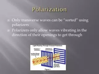
Polarization Angle Calibration by the Wiregrid rotation. Osamu Tajima (KEK) Presented by Hogan Nguyen (FNAL). Osamu’s Idea to Optimize All Modules Simultaneously in a Compact Footprint. The current grid: -motorized -no position encoding (sorry) -protection cover not shown.

E N D
Polarization Angle Calibrationby the Wiregrid rotation Osamu Tajima (KEK) Presented by Hogan Nguyen (FNAL)
Osamu’s Idea to Optimize All Modules Simultaneously in a Compact Footprint The current grid: -motorized -no position encoding (sorry) -protection cover not shown The first sparse grid to show proof-of-principle
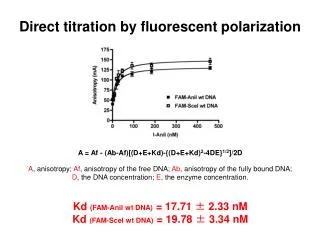
Sparse Wiregrid on the Deck ! Q1 U1U2Q2 Wiregrid was rotated counter clockwise (look sky from the module) Fitting PDF f(t; A0, A1, A2, w, d1, d2) = A0 + A1 cos(wt – d1) + A2 cos(2wt – d2) d2 polarization angle A2 demod gain (* w was treated as common fixed parameter for all the horns, its value is obtained from central horn fitting)
Relative Angles 0 deg. Look sky from module Same definition as qpoint:array_061509.txt 90 deg. Q1 U1U2Q2 00 64.60 +/- 0.22 +/- 2.75 +/- ? 108.25 +/- 0.23 +/- 2.75 +/- ? 17.77 +/- 0.23 +/- 2.75 +/- ? -32.67 +/- 0.24 +/- 2.75 +/- ? 01 80.67 +/- 0.23 +/- 2.75 +/- ? 125.42 +/- 0.25 +/- 2.75 +/- ? 36.07 +/- 0.25 +/- 2.75 +/- ? -14.41 +/- 0.23 +/- 2.75 +/- ? 02 78.37 +/- 0.27 +/- 2.75 +/- ? 118.28 +/- 0.27 +/- 2.75 +/- ? 28.10 +/- 0.26 +/- 2.75 +/- ? -15.24 +/- 0.23 +/- 2.75 +/- ? 03 71.87 +/- 0.24 +/- 2.75 +/- ? 114.86 +/- 0.26 +/- 2.75 +/- ? 23.90 +/- 0.25 +/- 2.75 +/- ? -23.72 +/- 0.23 +/- 2.75 +/- ? 04 61.87 +/- 0.26 +/- 2.75 +/- ? 106.70 +/- 0.26 +/- 2.75 +/- ? 17.00 +/- 0.27 +/- 2.75 +/- ? -35.70 +/- 0.25 +/- 2.75 +/- ? 05 70.40 +/- 0.27 +/- 2.75 +/- ? 112.57 +/- 0.27 +/- 2.75 +/- ? 24.54 +/- 0.26 +/- 2.75 +/- ? -25.59 +/- 0.27 +/- 2.75 +/- ? 06 69.50 +/- 0.26 +/- 2.75 +/- ? 112.29 +/- 0.25 +/- 2.75 +/- ? 22.01 +/- 0.24 +/- 2.75 +/- ? -28.53 +/- 0.27 +/- 2.75 +/- ? 07 59.27 +/- 0.24 +/- 2.75 +/- ? 106.16 +/- 0.26 +/- 2.75 +/- ? 16.52 +/- 0.26 +/- 2.75 +/- ? -35.05 +/- 0.26 +/- 2.75 +/- ? 08 68.80 +/- 0.27 +/- 2.75 +/- ? 112.66 +/- 0.27 +/- 2.75 +/- ? ------ +/- ------ +/- ----- +/- -28.03 +/- 0.27 +/- 2.75 +/- ? 09 75.65 +/- 0.24 +/- 2.75 +/- ? 118.06 +/- 0.25 +/- 2.75 +/- ? 25.85 +/- 0.25 +/- 2.75 +/- ? -22.50 +/- 0.26 +/- 2.75 +/- ? 10 66.97 +/- 0.26 +/- 2.75 +/- ? 109.04 +/- 0.28 +/- 2.75 +/- ? 20.36 +/- 0.27 +/- 2.75 +/- ? -30.00 +/- 0.27 +/- 2.75 +/- ? 11 68.23 +/- 0.25 +/- 2.75 +/- ? 112.69 +/- 0.26 +/- 2.75 +/- ? 24.92 +/- 0.26 +/- 2.75 +/- ? -27.25 +/- 0.23 +/- 2.75 +/- ? 12 69.70 +/- 0.27 +/- 2.75 +/- ? 113.20 +/- 0.25 +/- 2.75 +/- ? 23.87 +/- 0.25 +/- 2.75 +/- ? -25.81 +/- 0.28 +/- 2.75 +/- ? 13 54.66 +/- 0.27 +/- 2.75 +/- ? 97.83 +/- 0.27 +/- 2.75 +/- ? 8.98 +/- 0.26 +/- 2.75 +/- ? -42.24 +/- 0.26 +/- 2.75 +/- ? 14 63.47 +/- 0.25 +/- 2.75 +/- ? 108.16 +/- 0.25 +/- 2.75 +/- ? 16.24 +/- 0.25 +/- 2.75 +/- ? -32.22 +/- 0.23 +/- 2.75 +/- ? 15 55.24 +/- 0.21 +/- 2.75 +/- ? 110.73 +/- 0.25 +/- 2.75 +/- ? -3.13 +/- 0.22 +/- 2.75 +/- ? -38.93 +/- 0.22 +/- 2.75 +/- ? (degree) stat. error syst. absolute angle (1/4 bolts pitch on the cryostat, conservatively) Other syst. errors (possible bias, TP leakage, analysis methods etc.)
Comparison with Other Calibrations Wiregrid Moon Syst. diff. in Q1 & Q2 • Wiregrid • TauA 2-3 deg. Diff. in all diodes ? Moon TauA Syst. diff. in Q1 & Q2
Comparison with Other Calibrations (cont.) Wiregrid Moon Syst. diff. in Q1 & Q2 • Wiregrid • TauA 2-3 deg. Diff. in all diodes ? Moon TauA Syst. diff. in Q1 & Q2
Relative Demod Amplitude RQ_0000 Q1 0.623 0.001 U1 0.758 0.002 U2 0.696 0.002 Q2 0.505 0.001 RQ_0001 Q1 0.615 0.002 U1 0.913 0.003 U2 0.538 0.002 Q2 0.679 0.002 RQ_0002 Q1 0.550 0.002 U1 0.641 0.002 U2 0.455 0.001 Q2 0.468 0.001 RQ_0003 Q1 0.673 0.002 U1 0.794 0.003 U2 0.818 0.003 Q2 0.422 0.001 RQ_0004 Q1 0.693 0.002 U1 0.807 0.003 U2 0.675 0.002 Q2 0.594 0.002 RQ_0005 Q1 0.795 0.002 U1 0.500 0.001 U2 0.860 0.002 Q2 0.553 0.001 RQ_0006 Q1 0.557 0.001 U1 0.858 0.002 U2 0.868 0.002 Q2 0.463 0.001 RQ_0007 Q1 0.707 0.002 U1 0.917 0.003 U2 0.645 0.002 Q2 0.704 0.002 RQ_0008 Q1 0.868 0.002 U1 0.999 0.003 U2 0.000 0.000 Q2 0.506 0.001 RQ_0009 Q1 1.000 0.002 U1 0.961 0.002 U2 0.908 0.003 Q2 0.806 0.002 RQ_0010 Q1 0.695 0.002 U1 1.022 0.003 U2 0.924 0.002 Q2 0.558 0.001 RQ_0011 Q1 0.726 0.002 U1 0.715 0.002 U2 0.527 0.001 Q2 0.518 0.001 RQ_0012 Q1 0.710 0.002 U1 0.957 0.002 U2 0.814 0.002 Q2 0.513 0.001 RQ_0013 Q1 0.730 0.002 U1 0.982 0.003 U2 0.837 0.002 Q2 0.655 0.002 RQ_0014 Q1 0.885 0.002 U1 0.896 0.003 U2 0.600 0.002 Q2 0.721 0.001 RQ_0015 Q1 0.827 0.002 U1 0.812 0.003 U2 1.058 0.002 Q2 0.574 0.002 Possible systematic error has not been estimated, yet
Ratio of Relative Demod Amplitude to Relative gain obtained from skydips (normalized to center horn Q1) Q1 U1 U2 Q2 ratio ratio ratio ratio deg. Q1 U1 U2 Q2 deg. • Further Investigations are necessary to have conclusion • Most of them are lower than 1 while skydip uncertainty ~10% • Demod TP differences ? • TauA/skydip seems to have same tendency • How about Moon demod/TP ? • Outer radius ratio seems to be small !? • Wiregrid signal is not uniform on the array ? • Difference of solid angles from wire to ground screen, or other reason ? All Diodes average
Summary • We obtained Polarization angle and relative demod gain (signal height) by the sparse wiregrid calibration • Polarization Angle • Can be measured with less than 3 deg. accuracy while we have not finished all syst. error study • Wiregrid Moon : Several deg. diff for Q1 and Q2 • Wiregrid TauA : consistent while 2-3 deg. offsets • Relative Demod Gain • Cross checks with other calibrations are important
Possible Syst. Error Sources • Due to the protection UHMW-PE cover, its rotation effect is visible in total power clearly • Its systematic effect have to be estimated • Fitting can be improved, too (e.g. leakage is taken into account) • Wiregrid polarization signal is obtained from the reflection from all directions. However, top direction is sky temp.(10K) while both sides and bottom are 300K. It might make systematic for amplitude and pol. angle. These possible bias have to be estimated. • Contribution from 300K depends on the focal plane position, so magnitude of polarization signal may depend on the position within the array
Demod Total Power