Download
1 / 11
110 likes | 369 Vues
Polarization Calibration. Bryan Butler NRAO. Requirements. Dual polarization receivers – full simultaneous Stokes measurements when desired Polarization percentage measured to 0.1% Angle of linear polarization measured to 6 o. Requirements. FE Specs v 2.5

E N D
Polarization Calibration Bryan Butler NRAO
Requirements • Dual polarization receivers – full simultaneous Stokes measurements when desired • Polarization percentage measured to 0.1% • Angle of linear polarization measured to 6o
Requirements FE Specs v 2.5 • 4.2.1.1 Polarisation Optimization FEND-11010-ZZZ The polarisation performance shall be optimised for band 7. • 4.2.1.2 Polarisation States FEND-11110-ZZZ The front end shall simultaneously receive two orthogonal polarizations, with each converted to one or more IF outputs depending on mixing scheme. The nominal polarisation states shall be orthogonal. • 4.2.1.3 Polarisation alignment accuracy FEND-11210-ZZZ The orientation of each beam’s E-vector shall not deviate more than 2o peak-to-peak from the nominal. • 4.2.1.4 Cross-Polarisation FEND-11310-ZZZ At any frequency within the Front End's tuning range, the cross-polarised contribution within a signal channel shall be at least 20 dB below the desired polarisation. • 4.2.1.5 Polarisation mismatch FEND-11410-ZZZ The Front End contribution to the maximum polarisation mismatch between any pair of antennas in the array shall not exceed -20 dB.
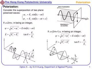
Theory Use Jones matrix formulation (Schwab 1979; Hamaker, Bregman, & Sault 1996), where the effect of a receiving system of antenna i on the polarization is represented by a combination of 2x2 matrices: Ji = Gi Di Pi where Gi is the “gain”: (p and q are polns) Di is the “leakage”: and Pi is the parallactic angle effect: linear circular
Theory the response of the interferometer v = (qq, qp, pq, qq) is: where s is the true Stokes visibility vector (i, q, u, v), and S is a coordinate transformation from the Stokes coordinate system to the system of the correlations: linear circular
Circular v. Linear Fundamentally, there is no difference. But, for circular feeds + receivers, the dominant error term in determining linear polarization is the leakage times Stokes I. For linear feeds + receivers, the dominant error term in determining linear polarization is the gain times Stokes I. It is generally easier to engineer better stability in leakage than in gain, so for good linear polarization capability, it is desirable to use circular polarization. BUT, it is also very difficult to provide good circular polarization performance over wide bandwidths (and, linear has lower noise). Long ago, the choice was made to use linear polarization for ALMA.
Implications • no polarization snapshots, unless gain & leakage extremely stable (need variation of c to break apart gain and leakage); • source and instrumental polarization not cleanly separated, so observation of a source of known polarization properties is required (astronomical or injected signal); • X-Y phase offset difficult to measure – need a strongly polarized astronomical source or injected signal; • could possibly get around some of this by rotating feeds with respect to each other – but might be problematic.
Possibilities • use astronomical sources – the question here is whether we can meet the requirements with this alone? • use an injected signal. this is preferable in many ways, but we need to develop a way of generating and injecting the signal (either at RF or IF) and controlling the polarization characteristics of that signal. we were considering a photonic device in the subreflector, but it may not be stable enough. can we use the wire grid load system to do this (might require a rotation of the grid)?
Other Calibrations • cross-hand delays; • cross-hand voltage patterns; • single dish issues.
¼ wave plate for the most precise linear polarization work, there is fear that we will not be able to calibrate to the required level, so we have designed a ¼ wave plate to be inserted in front of the band 7 feed (a ¼ wave plate at 450 converts from linear to circular polarization). problem is that this introduces noise, and is relatively narrow band. but it is deemed necessary for this precision linear polarization science.
Problems • some specs problems – circular polarization, timescale on stability, etc… • scattering from atmospheric particles, especially in the submm (e.g., pol’n from cirrus can be serious – modal particle size is 10-100 m, depth can be 1-2 km, opacity can be 6% at 220 GHz, and scales with frequency); • mosaics; • pad perpendicularity issue; • NO MANPOWER!