Download
1 / 44
450 likes | 570 Vues
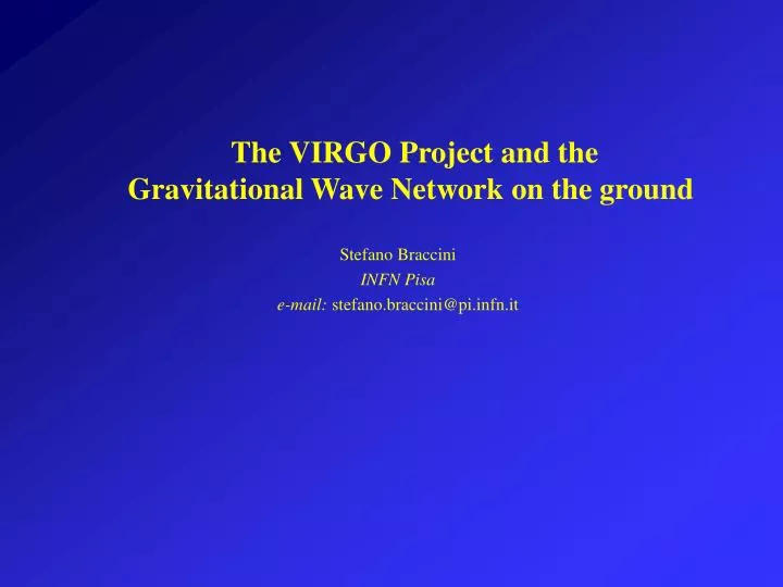
The VIRGO Project and the Gravitational Wave Network on the ground. Stefano Braccini INFN Pisa e-mail: stefano.braccini@pi.infn.it. 1) Introduction 2) Working Principle 3) Status of VIRGO 4) Interferometer Network 5) The Future. L ~ 10 3 m. D L ~ 10 -18 m.

E N D
The VIRGO Project and theGravitational Wave Network on the ground Stefano Braccini INFN Pisa e-mail: stefano.braccini@pi.infn.it
1) Introduction • 2) Working Principle • 3) Status of VIRGO • 4) Interferometer Network • 5) The Future
L ~ 103m DL ~ 10-18m h ~ 10-21 (VIRGO Supernova) Interferometric Detection L-DL L+DL t = 0 t = T /4 t = T/2 t = 3T /4 t = T
NS or BH Coalescing Binaries …minutes… kHz Hz chirp h Signals can be exactly computed (except for final part) Time Sources
Sources Supernova Bursts Pulse of ms duration (no template available)
Emits periodic signals at f=2fspinbut ….weak Sources Neutron Stars SNR can be increased by integrating the signal for long time (months) Importance of a low frequency sensitivity (Hz region)
Wide variety of signals expected between fraction of Hz and a few kHz
1) Introduction • 2) Working Principle • 3) Status of VIRGO • 4) Interferometer Network • 5) The Future
h = 10-21 fgw= 3·10-11 rad A simple detector
Fabry-Perot Cavities to increase the effect Increase beam phase shift by 2F/p
1 kW 20 W Optical Readout Noise An accurate measurement of the phase requires a large amount of photons…
Thermal Noise • Fluctuation-dissipation theorem Reduce dissipations in the optical payload
Strong vibration filtering by a chain of mechanical low frequency oscillators in 6 dof Transmission frequency Seismic Noise
Seismic Attenuation Low Dissipations Recycling High Power Laser Summary of the technique Fabry-Perot photodiode Vacuum
Seismic Thermal Shot What is a sensitivity curve ?
SPACE GROUND Advanced resonant Ground and Space are complementary
3 km Ground-Based Network 600 m TAMA 4 & 2 km 300 m AIGO 4 km
1) Introduction • 2) Working Principle • 3) Status of VIRGO • 4) Interferometer Network • 5) The Future
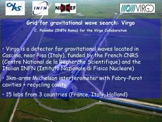
LAPP – Annecy • INFN – Firenze-Urbino • INFN – Frascati • IPN – Lyon • INFN – Napoli VIRGO • OCA – Nice • LAL – Orsay • ESPCI – Paris • INFN – Perugia • INFN – Pisa • INFN – Roma VIRGO at EGO Site
VIRGO Optical Scheme Input Mode Cleaner (144 m) 3 km long Fabry-Perot Cavities Laser 20 W Power Recycling Output Mode Cleaner (4 cm)
Superattenuators Magnetic antisprings Blade springs Extend the band down to a few Hz
Photodiode demodulated signal during resonance crossing Mirror Surface HOOK CAVITIES AT RESONANCE USING MIRROR COIL-MAGNET ACTUATORS l/2 Resonance Crossing l /100 Interferometer Locking 0.5 mm/s MIRROR SWING
Interferometer Control Quadrants and Photodiodes to close angular and longitudinal feedbacks aimed to keep the VIRGO cavities aligned and at resonance
C5 recycled May 27th, recycled Beam Splitter Control Improvements Photodiode Noise Reduction Reduced Beam Splitter DAC noise Noise Hunting and Reduction Measure the sensitivity Identify the noise sources Try to reduce the noise
Present Status After a few months long stop (to upgrade the injection bench) VIRGO restarted the activities on January 06 Long term scientific run with sensitivities similar to LIGO scheduled for September 2006
Six working groups settled up inside Virgo since 1998 h Reconstruction Noise analysis & data quality Coalescing binaries Bursts Periodic sources Stochastic background VIRGO Data Analysis Agreement for a coherent data analysis withLIGO will be implemented in the next weeks
1) Introduction • 2) Working Principle • 3) Status of VIRGO • 4) Interferometer Network • 5) The Future
LIGO • 3 ITF: Hanford (4 km, 2 km), Livingston (4 km) • Same optical scheme as VIRGO, simpler suspensions • Two science runs already performed
LIGO Commissioning LIGO is in action at the design sensitivity
Long term scientific run (S5) started on November 2005 in order to accumulate 1 year of data
Long term scientific run (S5) started on November 2005 in order to accumulate 1 year of data Double Coincidence: 66.7% - Triple Coincidence: 38.4 %
Long term scientific run (S5) started on November 2005 in order to accumulate 1 year of data Duty cycle is increasing……
3 km 600 m 600 m LONG TERM RUN IS STARTING Ground-Based Network TAMA 4 & 2 km 300 m AIGO 4 km
1) Introduction • 2) Working Principle • 3) Status of VIRGO • 4) Interferometer Network • 5) The Future
Short Term 2006 - 2007 Network -18 10 -19 10 -20 10 -21 10 -22 10 -23 10 -24 10 4 1 10 100 1000 10 2006-2007 Network h/Hz1/2 LIGO Virgo Resonant Pulsars Antennas 2007 h , 1 year integration GEO BH-BH Merger max Oscillations @ 100 Mpc Core Collapse QNM from BH Collisions, @ 10 Mpc QNM from BH Collisions, 100 - 10 Msun, 150 Mpc 1000 - 100 Msun, z=1 BH-BH Inspiral, 100 Mpc NS-NS Merger Oscillations @ 100 Mpc BH-BH Inspiral, z = 0.4 -6 e NS, =10 , 10 kpc NS-NS Inspiral, 300 Mpc Hz NS-NS NS-BH BH-BH SNe Event Rate (per year)310-4 - 0.3 4 10-4 - 0.5 10-3 - 3 0.05 Range (Mpc)30 60 145 0.1 Scarce probability of a first detection
VIRGO+ and LIGO+ Slight upgradings of the present design (a few months long stops) Higher laser power (several tens of W) Monolithic mirror suspensions Control Noise Reduction
Medium Term 2008 - 2013 Network NS-NSNS-BHBH-BHSNe Event Rate (per year)0.025-10 10-3-15 3 10-2-90 1 Range (Mpc)114 230 584 10 A first detection is likely
Advanced LIGO (2013) Next Generation Higher power (10 W180 W) New isolation system (active) Fused silica suspension wires 40 kg fused silica mirrors Signal recycling Similar program for Advanced VIRGO VIRGO
Two underground 3 km itfs with mirrors at 20 K in the same vacuum system (Kamioka) – data taking 2012 LCGT project CERN – C.A.P.P. workshop – June 16th, 2003 G.Losurdo – INFN Firenze-Urbino
Long Term Beyond 2013 …+ LISA (launch 2015) NS-NS NS-BH BH-BH SNe Event Rate3/yr - 4/day 1/yr - 6/day 3/month - 30/day 20 Range (Mpc)Event300 750 z=0.45 100 Detection is “sure”
+ ITFs 2009 Advanced Network 2013 NS/NS detectable at 300 Mpc Virgo VIRGO-LIGO 2006
LIGO and VIRGO will perform joint data analysis, coordinating running, shutdowns, etc. to maximize GW science
FIRST DETECTION UNLIKELY DETECTION LIKELY LISA GW ASTROPHYSICS CONCLUSIONS LIGO long term run in progress (S5) GEO and VIRGO will join LIGO in this year LIGO+ and VIRGO+ will enter in action after 2008-09 Advanced Network (beyond 2013)