Download
1 / 25
250 likes | 253 Vues
The status of VIRGO Edwige Tournefier (LAPP-Annecy ) for the VIRGO Collaboration HEP2005, 21 st - 27 th July 2005. The VIRGO experiment and detection of gravitational waves The commissioning of VIRGO Conclusions. French-italian collaboration (CNRS – INFN)

E N D
The status of VIRGOEdwige Tournefier (LAPP-Annecy ) for the VIRGO CollaborationHEP2005, 21st- 27th July 2005 • The VIRGO experiment and detection of gravitational waves • The commissioning of VIRGO • Conclusions
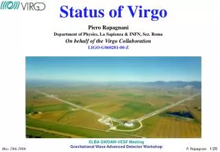
French-italian collaboration (CNRS – INFN) Annecy (LAPP), Firenze, Frascati, Lyon (LMA), Napoli, Nice (OCA), Paris (ESPCI), Perugia, Pisa, Roma, Orsay (LAL) Virgo site : Cascina close to Pisa Virgo goal: detection of gravitational waves VIRGO
How to detect gravitational waves? Suspended mirror Suspended mirror Beam splitter Light Detection LASER () • Effect of a gravitational wave on free masses: • A Michelson interferometer is suitable: • suspend mirror with pendulum => ‘free falling masses’ • Gravitational wave => phase shift • Measure: h = L/L • L = length difference between the 2 arms • L = arm length
The shot noise and the VIRGO optical design 1/ Fabry-Perot cavities to increase the effective length: ( F = finesse ) => L’ = 100km for L=3km and F=50 2/ Recycling mirror to increase the effective power: P’ = R P (R = recycling gain) => P’ = 1kW with P=20W and R=50 Gravitational wave signal Limitation of a Michelson interferometer due to photon shot noise: the minimum measurable relative displacement is =>Can reachh ~ 3.10-23 withL=100kmandP=1kW How to achieve that?
Noise sources in interferometers Seismic Noise Acoustic Noise Thermal Noise Index fluctuation Shot Noise Detection Noise Laser Noises
Noise sources: seismic noise 1014 • Seismic noise spectrum for f few Hz: • a ~ 10-6 - 10-7 • shot noise ! • Need a very large attenuation! Solution: suspend the mirrors to a chain of pendulums Transfert function • With a chain of 6 pendulums: attenuation of the seismic noise by ~1014 at 10 Hz !
Suspensions and control of the interferometer All mirrors are suspended to a cascade of pendulums: • Large attenuation in the detection band ( > 10 Hz) • Large residual motion at low frequencies: < ~1mm • Need active controls to: • maintain the interferometer’s alignment • maintain the required interference conditions The control is done in 2 steps: 1/ Local control of the suspensions: • Residual motion ~2 m/sec • Obtain interference fringes 2/ To keep the interferometer at interference conditions: • Need to control the length of the cavities to 10-12 m • Need to keep the interferometer aligned • Use the interferometer signals: photodiodes
VIRGO design sensitivity Shot noise 1 Main sources of noise limiting the VIRGO design sensitivity Seismic noise Thermal noise Shot noise
Gravitationnal wave sources and VIRGO design sensitivity • Coalescing binaries (1.4 Mo) • Pulsars: upper limit (1 year) • Supernovae at 15Mpc Distance to the Virgo cluster = 10Mpc
The commissioning of VIRGO • control of the north FP cavity: Oct 2003 • - control of the west FP cavity: Dec 2003 - recombined (Michelson) ITF: Feb 2004 - recycled (full VIRGO) ITF: Oct 2004 Fabry-Perot cavities input mode cleaner l=150m beam splitter laser l=6m L=3km recycling mirror output mode cleaner • Technical runs (3 to 5 days) at each step • C1(Nov 2003),…, C5(Dec 2004) • Lock stability • Sensitivity/noise studies • Data taking on ‘long’ period • End of construction: 2003 • The steps of the VIRGO commissioning: West arm North arm Gravitational wave signal
The lock of the full VIRGO + Power stored in the recycling cavity (Watts) Lock acquisition With recycling Recycling gain ~ 30 Laser - Without recycling • Lock of the recycled interferometer (full VIRGO): • Need to control 4 degrees of freedom (3 cavities + Michelson on dark fringe) • The lock is acquired in several steps (‘variable Finesse’ strategy): • Start without recycling • Slowly increase the recycling gain and move to the dark fringe
Sensitivity summary Single arm, P=7 W Recombined, P=7 W Recycled, P=0.7 W P = 10W h ~3. 10-21/Hz
Typical unforeseen difficulties • Injection bench: • A small fraction (bigger than expected) of the light reflected by the interferometer is retro-diffused by the input mode cleaner mirror • spurious interferences Temporary solutions: - tried to rotate the mode cleaner mirror - reduce the incident light (/10) • We are now working with only Pin = 0.7 Watts Final solution: install a Faraday isolator • A new input bench will be installed in September 2005 Frequency noise Recycling mirror: - aligned - not aligned
Present sensitivity and perspectives - local angular controls - longitudinal controls - low noise actuators P=0.7 W P = 10W • Futur: the VIRGO sensitivity will significantly improve with • full power(new input bench) • the automatic alignment of the interferometer (global angular control) • the improvement of the longitudinal controls • lower noise actuators • … • Improvements since C5: Shot noise for P=0.7 W
Data analysis: some examples - Injected events • Test of the data analysis on real data from the technical runs: • Test the full chain of data analysis • Learn how to put vetoes • Inject events in the real data: software and hardware injections -> measure efficiencies, false alarm rate,… • Start collaboration with LIGO: Coincident analysis will help the detection of GW =>decrease false alarm rate (rare events in a non gaussian noise) Combined data analysis is necessary to extract the source parameters Event amplitude Quiet period Event amplitude
Conclusion • The recycled (full VIRGO) interferometer is working • Next engineering run (C6), 29/07-12/08: 2 weeks of data taking with the best sensitivity • The sensitivity will make big progress with • New input bench (-> full input power) • Automatic alignment of the mirrors • The data analysis is been prepared and tested on real data Collaboration with LIGO is starting • First scientific run in 2006/7?
Noise studies Sensitivity measured during C4 run and identified sources of noise Noise hunting: 1/ Identify the sources of noise which limit the sensitivity 2/ Perform the necessary improvements / implement new controls
Comparison with LIGO first science run (S1) Virgo May 2005
Example of lock acquisition Power stored inside the Fabry-Perot cavity /2 Error signal of the cavity Lock acquisition: Apply force on the mirror to keep the error signal at zero Correction sent to the actuators of the mirror Mirror 4 seconds Magnet Coil Example of the lock acquisition of a Fabry-Perot cavity Photodiode used for lock acquisition
The commissioning of the CITF unit = meters! • Commissioning of the central interferometer: 09/2001 -> 07/2002 • CITF = Recycled Michelson interferometer (no Fabry-Perot cavities) • a lot of common points with VIRGO • The evolution: configuration and sensitivity: 4 runs of 3 days each - E0/E1: Michelson - E2: Recycled Michelson - E3: + automatic angular alignment - E4: + final injection system • Results: • Viability of the controls • Sensitivity curve understood • And gain experience for the VIRGO commissioning - Improvements triggered by the CITF experience
The mirrors • Fused silica mirrors • Coated in a class 1 clean room at SMA-Lyon (unique in the world). • Low scattering and absorption: < few ppm • Good uniformity on large dimension: < 10-3 400 mm • Large mirrors (FP cavities): • 35 cm, 10 cm thick • 20 kg
The injection and detection systems • Laser: powerful and stable • 20W • Power stability: 10-8 • Frequency stability: Hz • The input and output mode cleaners: • optical filter => improve signal to noise ratio • Signal detection: • - InGaAs photodiodes, high efficiency
Future: how to improve the sensitivity? Shot noise The first generation of detectors might not be able to see gravitational waves • Need to push the sensitivity further down: • Seismic noise: • The VIRGO suspensions already meet the requirements for next generation interferometers • The main limit: thermal noise • Monolitic suspensions (silica) • Better mirrors (material, geometry, coating) • Shot noise • More powerful lasers • Signal recycling technique • And the technical noises • Better sensors • Better electronics • Better control systems
Recombined interferometer Example of lock acquisition Power ‘stored’ inside the FP cavities Power at the interferometer output Lock on the dark fringe • Recombined interferometer: keep the two Fabry-Perot cavities on resonance + the Michelson on the dark fringe