Download
1 / 32

E N D
Background Information for:Green Power EMC High School Physical Science/Physics/Chemistry Unit Plan #3: “How Solar Cells Work: Investigating Electron Flow”AUTHOR(S): Sharmistha Basu-dutt1, Ph.D.; Tyson H. Harty2, Ph.D.; Julie Talbot3, Ph.D.1Department of Chemistry, University of West Georgia, Carrollton, GA 2Jasper County High School, Monticello, GA3Department of Physics, University of West Georgia, Carrollton, GATITLE OF THE UNIT: Investigating mechanisms of electron flow in mechanical and biological systems involving solar energytransferGRADE LEVEL/SUBJECT: HS Physical Science, HS Chemistry, HS Physics
What is photovoltaic? • “Photovoltaic" has two parts: photo, derived from the Greek word for light, and volt, relating to electricity pioneer Alessandro Volta • Becquerel discovered the process of using sunlight to produce an electric current in a solid material. • Photoelectric or photovoltaic effect caused certain materials to convert light energy into electrical energy at the atomic level. • Photovoltaic (PV)/solar materials & devices convert energy from sunlight into electrical energy. http://www.youtube.com/watch?feature=player_embedded&v=0elhIcPVtKE
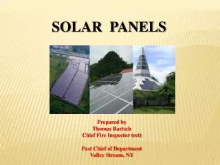
PV Systems in our daily life • Simple PV systems provide power for small consumer items such as calculators and wristwatches. • More complicated systems provide power for communications satellites, water pumps, and the lights, appliances, and machines in some homes and workplaces. • Many road and traffic signs also are now powered by PV.
History of PV • 1954 - first practical PV cell developed by Bell Telephone researchers examining the sensitivity of a properly prepared silicon wafer to sunlight. • Late 1950s - PV cells used to power U.S. space satellites. • 1980s - PV cells used widely for small consumer electronics like calculators and watches and to provide electricity in remote or "off-grid" locations where there were no electric power lines. • 1990s - Technology advances and government financial incentives have helped to greatly expand PV use for "grid-connected" systems on homes, buildings, and central-station power facilities. • 2012 - U.S. shipments (includes imports, exports, and domestic shipments) of PV panels (modules) was the equivalent of about 4,655 Megawatts, about 245 times greater than the shipments of about 19 Megawatts in 1994.
Advantages of PV systems • Conversion from sunlight to electricity is direct, so bulky mechanical generator systems are unnecessary. • PV arrays can be installed quickly and in any size. • The environmental impact is minimal, requiring no water for system cooling and generating no by-products.
Type of current from PV • Photovoltaic cells, like batteries, generate direct current (DC), which is generally used for small loads (electronic equipment). • When DC from photovoltaic cells is used for commercial applications or sold to electric utilities using the electric grid, it must be converted to alternating current (AC) using inverters, solid state devices that convert DC power to AC.
History of PV materials • 1904 - Wilhelm Hallwachs (German) discovered that a combination of copper and cuprous oxide was sensitive to light. • 1905 - Albert Einstein published a paper on the photoelectric effect. 1921 Nobel Prize . • 1950s - Inventors at Bell Labs developed a more efficient (6%) PV cell made from silicon. 1st solar cell capable of generating power from the sun to run everyday electrical equipment. • 1955 - Western Electric sells commercial licenses for silicon PV technologies such as dollar bill changers and decoders for computer punch cards and tape. • 1958 - Federal support for PV technology initially tied to the space program to power for the Vanguard satellite. • 1973 - Spurred by the oil embargo, interest in space applications of PV grew. • 1970s – • MIT developed a program for the development of distributed PV focusing on design and demonstration issues for the buildings sector. • 1978 Energy Tax Act established a 10% investment tax credit for PV applications;. • 1978 Solar Photovoltaic Energy, Research, Development and Demonstration Act committed $1.2 billion, over 10 years, to improve PV production levels, reduce costs, and stimulate private sector purchases. Federal facilities installed PV systems.
1980 - The Carlisle house (Massachusetts) was the first building with integrated PV system, passive solar heating and cooling, superinsulation, internal thermal mass, earth-sheltering, daylighting, a roof-integrated solar thermal system, and a 7.5-peak-watt PV array of polycrystalline modules. • 1985 - 6 MW Carissa Plains plant added to Southern California Edison’s system, later dismantled. • 1989 - Renewable Energy and Energy Efficiency Technology Competitiveness Act to improve the operational reliability of PV modules, increase module efficiencies, decrease direct manufacturing costs, and improve electric power production costs • 1990 –PV Manufacturing Technology (PVMaT) project began to improve manufacturing processes, accelerate manufacturing cost reductions for PV modules, improve commercial product performance, and lay the groundwork for a substantial scale-up of manufacturing capacity. • 1992 - The University of South Florida fabricated a 15.89% efficient thin-film cell, breaking the 15% barrier for the first time • 1993 - Pacific Gas and Electric completed installation of the first grid-supported PV system in Kerman, California. The 500 KW system was aimed at “distributed power,” whereby a relatively small amount of power is carefully matched to a specific load and produced near the point of consumption. • 1993 - New world-record efficiencies in polycrystalline thin film and in single-crystal devices, approaching 16% and 30%, respectively, were achieved. • 1994 - The National Renewable Energy Laboratory (NREL) developed a solar cell made of gallium indium phosphide and gallium arsenide that exceeded 30% conversion efficiency. • 1995 - An Amoco-Enron joint venture announced its intention to use amorphous silicon modules for utility-scale PV applications.
1998 – Invention of flexible solar shingles, a roofing material and state-of-the-art technology for converting sunlight into electricity on buildings. • 1999 - Construction was completed on Four Times Square in New York, New York. Which had more energy-efficient features than any other commercial skyscraper • 1999 - Spectrolab, Inc., and the NREL develop a 32.3% efficient solar cell. The high efficiency resulted from combining three layers of photovoltaic materials into a single cell. Researchers at the NREL developed a record-breaking prototype solar cell that measured 18.8% efficiency, topping the previous record for thin-film cells by more than 1%. Worldwide, installed photovoltaic capacity reached 1,000 megawatts. • 2000 - First Solar began production at the Perrysburg, Ohio, photovoltaic manufacturing plant. Each year, it could produce enough solar panels to generate 100 megawatts of power. Astronauts began installing solar panels at the International Space Station, on the largest solar power array deployed in space. Each "wing" of the array consisted of 32,800 solar cells. • 2001 - BP and BP Solar announced the first BP Connect gasoline retail and convenience store in the United States. The Indianapolis, Indiana, service station features a solar-electric canopy. The canopy contains translucent PV modules made of thin-film silicon integrated into glass. • 2007 - Boeing Spectrolab and the NREL created the High-Efficiency Metamorphic Multijunction Concentrator Solar Cell, or HEMM solar cell, which achieved the highest efficiency level of any PV device to date. The HEMM solar cell broke the 40% conversion efficiency barrier, making it twice as efficient as a typical silicon cell.
PV Materials • Most commonly made of semiconductors such as silicon. • When light strikes the cell, a certain portion of it is absorbed within the semiconductor material. • The energy knocks electrons loose, allowing them to flow freely. • One or more electric fields act to force freed electrons to flow in a certain direction causing current. • Metal contacts placed on the top and bottom of the PV cell allow current to be drawn off for external use (eg. power a calculator). • This current plus the cell's voltage (result of built-in electric field or fields) defines the power (or wattage) that the solar cell can produce.
Step 2 - Flow of electricity Step 1 - Photons carry solar energy • When the electrons leave their position, holes are formed. When many electrons, each carrying a negative charge, travel toward the front surface of the cell, the resulting imbalance of charge between the cell's front and back surfaces creates a voltage potential like the negative and positive terminals of a battery. When the two surfaces are connected through an external load, such as an appliance, electricity flows. • Sunlight is composed of photons, or particles of solar energy. These photons contain various amounts of energy corresponding to the different wavelengths of the solar spectrum. • When photons strike a photovoltaic cell, they may be reflected, pass right through, or be absorbed. Only the absorbed photons provide energy to generate electricity. When enough sunlight (energy) is absorbed by the material (a semiconductor), electrons are dislodged from the material's atoms. Special treatment of the material surface during manufacturing makes the front surface of the cell more receptive to free electrons, so the electrons naturally migrate to the surface.
Dye sensitized solar cell (DSC) • Low-cost thin film solar cell. • Modern version of DSC invented by Michael Grätzel in 1988, known as the Grätzel cell. • Engineered in layers: a photosensitive layer made of ultrathin, nano-sized semiconductor crystals over a thin layer of titanium dioxide. When photons (from sunlight) hit the photosensitive layer, the freed electrons accumulate on the layer of titanium dioxide and create an electrical current. Previously, a liquid electrolyte was needed to carry the electrons from one layer to another but in the newest generation of Grätzel cells, a dye made of amorphous organic material is used to coat the titanium dioxide -- the dye absorbs light and attracts excited electrons, which generates a charge. • DSC technology is highly efficient compared to other forms of solar cells, producing efficiencies greater than 11 percent -- meaning that 11 percent of the captured solar energy is converted to electrical energy -- rather than 4 to 5 percent
Graetzl Cell Materials • Two transparent conducting oxide glass plates are sandwiched together. • A thin fluorine-doped indium oxide or tin-doped indium oxide coating on one side of the glass makes the glass surface electrically conducting. • The upper plate is the 'photoanode' with a sensitizing dye adsorbed onto a layer of randomly-stacked TiO2 . • The lower plate has a thin film of platinum chemically deposited or simply coated with graphite (from a soft pencil) to act as a conductor and catalyst. • The upper and lower plates are secured together with a clamp. • To finish the cell, a drop of organic electrolyte solution, which contains the iodide/tri-iodide redox couple, is applied between the plates.
Working of Graetzl Cell – 5 steps • Photons from solar energy are trapped by the dye sensitizer (S) and cause the electrons in the dye to become photo-excited (S*): • S(adsorbed on TiO2) + hn S*(adsorbed on TiO2) • Excited electrons escape from the dye molecules: • S*(adsorbed on TiO2) S+(adsorbed on TiO2) + e- • Free electrons then move through the conduction band of TiO2, gather at the anode (the dyed TiO2 plate), and then start to flow as an electric current through the external load to the counter electrode (graphite coated plate). • The oxidized dye (S+) is reduced to the original form (S) by regaining electrons from the organic electrolyte solution that contains the iodide/tri-iodide redox system, with the iodide ions being oxidized (loss of electrons) to tri-iodide ions: • S+(adsorbed on TiO2) + 3/2I- S(adsorbed on TiO2) + ½I3- • To restore the iodide ions, free electrons at the counter (graphite) electrode (which have travelled around the circuit) reduce the tri-iodide molecules back to their iodide state. The dye molecules are then ready for the next cycle.
Operation of PV systems • The photovoltaic cell is the basic building block of a photovoltaic system. • Individual cells can vary in size from about 0.5 inches to about 4 inches across. • One cell only produces 1 or 2 watts, which isn't enough power for most applications. • To increase power output, cells are electrically connected into a packaged weather-tight module. • Modules can be further connected to form an array – refers to the entire generating plant, whether it is made up of one or several thousand modules. • The number of modules connected together in an array depends on the amount of power output needed.
Weather affects PV • The performance of a photovoltaic array is dependent upon sunlight. • Climate conditions (such as clouds or fog) have a significant effect on the amount of solar energy received by a photovoltaic array and, in turn, its performance. • The efficiency of most commercially available photovoltaic modules in converting sunlight to electricity ranges from 5% to 15%. • Researchers around the world are trying to achieve efficiencies up to 30%.
Solar thermal power plants • Solar thermal power plants use the sun's rays to heat a fluid to very high temperatures. The fluid is then circulated through pipes so it can transfer its heat to water to produce steam. The steam, in turn, is converted into mechanical energy in a turbine and into electricity by a conventional generator coupled to the turbine. • Solar thermal power generation works essentially the same as generation from fossil fuels except that instead of using steam produced from the combustion of fossil fuels, the steam is produced by the heat collected from sunlight. • Solar thermal technologies use concentrator systems to achieve the high temperatures needed to heat the fluid. • Three types – parabolic trough, solar dish, solar power tower.
Parabolic trough collector • Most common. • A parabolic trough collector has a long parabolic-shaped reflector that focuses the sun's rays on a receiver pipe located at the focus of the parabola. The collector tilts with the sun as the sun moves from east to west during the day to ensure that the sun is continuously focused on the receiver. Used in the largest solar power facility in the world located in the Mojave Desert at Kramer Junction, California. This facility has operated since the 1980s and accounts for the majority of solar electricity produced by the electric power sector today.
Because of its parabolic shape, a trough can focus the sun at 30 to 100 times its normal intensity (concentration ratio) on the receiver pipe located along the focal line of the trough, achieving operating temperatures over 750°F. • The "solar field" has many parallel rows of solar parabolic trough collectors aligned on a north-south horizontal axis. A working (heat transfer) fluid is heated as it circulates through the receiver pipes and returns to a series of "heat exchangers" at a central location. Here, the fluid circulates through pipes so it can transfer its heat to water to generate high-pressure, superheated steam. The steam is then fed to a conventional steam turbine and generator to produce electricity. When the hot fluid passes through the heat exchangers, it cools down, and is then re-circulated through the solar field to heat up again. • The plant is usually designed to operate at full power using solar energy alone, given sufficient solar energy. On low solar energy (cloudy/rainy) days, these plants can use fossil fuel combustion to supplement the solar output.
Solar dish/engine • A solar dish/engine system uses concentrating solar collectors that track the sun, so they always point straight at the sun and concentrate the solar energy at the focal point of the dish. • A solar dish's concentration ratio is much higher than a solar trough's, typically over 2,000, with a working fluid temperature over 1380°F.
The power-generating equipment used with a solar dish can be mounted at the focal point of the dish, making it well suited for remote operations or, as with the solar trough, the energy may be collected from a number of installations and converted to electricity at a central point. • The engine in a solar dish/engine system converts heat to mechanical power by compressing the working fluid when it is cold, heating the compressed working fluid, and then expanding the fluid through a turbine or with a piston to produce work. The engine is coupled to an electric generator to convert the mechanical power to electric power.
Solar power tower • A solar power tower, or central receiver, generates electricity from sunlight by focusing concentrated solar energy on a tower-mounted heat exchanger (receiver). • This system uses hundreds to thousands of flat, sun-tracking mirrors called heliostats to reflect and concentrate the sun's energy onto a central receiver tower. • The energy can be concentrated as much as 1,500 times that of the energy coming in from the sun.
Energy losses from thermal-energy transport are minimized because solar energy is being directly transferred by reflection from the heliostats to a single receiver, rather than being moved through a transfer medium to one central location, as with parabolic troughs. • Power towers must be large to be economical. This is a promising technology for large-scale grid-connected power plants. • Power towers are in the early stages of development compared with parabolic trough technology.
Concentrating Solar Power (CSP) • CSP plants produce power • by first using mirrors to focus sunlight to heat a working fluid. • The high-temperature fluid is used to spin a turbine or power an engine • This drives a generator and produces electricity. From towers to dishes to linear mirrors to troughs, concentrating solar power (CSP) technologies reflect and collect solar heat to generate electricity.
Types of CSP - Linear Linear concentrating collector fields consist of a large number of collectors in parallel rows that are typically aligned in a north-south orientation to maximize annual and summer energy collection. With a single-axis sun-tracking system, this configuration enables the mirrors to track the sun from east to west during the day, which ensures that the sun reflects continuously onto the receiver tubes.
Types of CSP – Parabolic Trough The receiver tube is positioned along the focal line of each parabola-shaped reflector. The tube is fixed to the mirror structure, and the heated fluid—either a heat-transfer fluid or water/steam—flows through and out of the field of solar mirrors to where it is used to create steam (or, in the case of a water/steam receiver, it is sent directly to the turbine).
Types of CSP – Dish The solar concentrator, or dish, gathers the solar energy coming directly from the sun. The resulting beam of concentrated sunlight is reflected onto a thermal receiver that collects the solar heat. The dish is mounted on a structure that tracks the sun continuously throughout the day to reflect the highest percentage of sunlight possible onto the thermal receiver.
Types of CSP – Power Tower Numerous large, flat, sun-tracking mirrors, known as heliostats, focus sunlight onto a receiver at the top of a tall tower. A heat-transfer fluid heated in the receiver is used to generate steam, which, in turn, is used in a conventional turbine generator to produce electricity.