Download
1 / 16
160 likes | 327 Vues
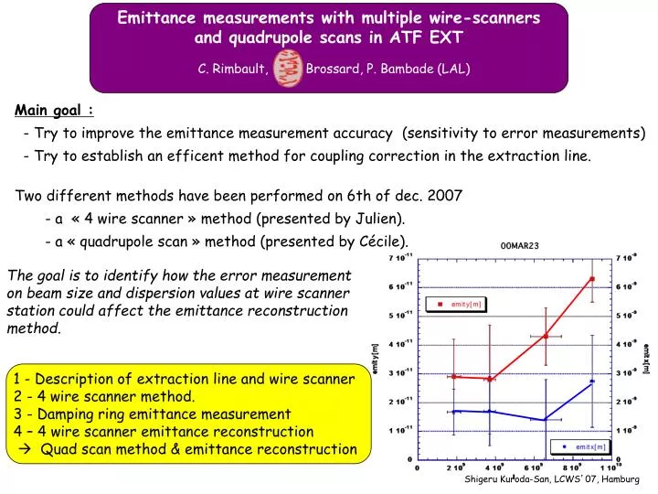
Shigeru Kuroda-San, LCWS ’ 07, Hamburg. Emittance measurements with multiple wire-scanners and quadrupole scans in ATF EXT. C. Rimbault, Brossard, P. Bambade (LAL). Main goal : - Try to improve the emittance measurement accuracy (sensitivity to error measurements)

E N D
Shigeru Kuroda-San, LCWS’07, Hamburg Emittance measurements with multiple wire-scanners and quadrupole scans in ATF EXT C. Rimbault, Brossard, P. Bambade (LAL) Main goal : - Try to improve the emittance measurement accuracy (sensitivity to error measurements) - Try to establish an efficent method for coupling correction in the extraction line. Two different methods have been performed on 6th of dec. 2007 - a « 4 wire scanner » method (presented by Julien). - a « quadrupole scan » method (presented by Cécile). The goal is to identify how the error measurement on beam size and dispersion values at wire scanner station could affect the emittance reconstruction method. 1 - Description of extraction line and wire scanner 2 - 4 wire scanner method. 3 - Damping ring emittance measurement 4 – 4 wire scanner emittance reconstruction Quad scan method & emittance reconstruction
Extraction line Damping Ring Injection
1 - ATF EXT line description & wire scanner position 5 wire scanners station Diagnostic section (hx=hy =0) At each station, there are different wire scanner orientation for beam size and shape measurement. For vertical (or horizontal) projected emittance measurement, only one wire scanner orientation is needed. For x-y coupling measurement a tilt angle is also required. 90° 10° 0° Wire thickness = 10 mm & 50 mm
2 - Multi-wire scanner emittance reconstruction method No optic coupling between reference point and wire scanner position the following linear system is used to reconstruct the vertical projected emittance. Rij Linear transport coefficent Beam matrix element at the reference point « A ». at the 5 wire scanners station 10° measurements to defined 4 5 7 and 8 x measurements to defined 1 2 and 3 The y-beam size are corrected from wire scanner diameter dy_wire and dispersion y (assuming p/p= 8.10-4) The reference point « A » is just in front MW0X wire scanner. We will focused on projectedy emittance (the other components will be analysed later). The Least Means Square Method (LMS) is used to find « the LMS solution ». Then the projected emittancey is computed using :
3 - Damping ring emittance measurement Results obtained from the shift 6 dec 2007. (SET file : SET07DEC6_1732.dat) Beam tuning in DR : Orbit, dispersion and coupling correction Emittance measurement in DR using XSR x-beam size = 15 m y-beam size = 34 m x =0.399 m y =3.091 m In the damping ring : ->x ~ 2.9 nm.rad ~ 1.5* nom. value (2 nm.rad ) ->y ~ 72 pm.rad ~ 3.6* nom value (20 pm.rad)
before /after before /after 4 - wire scanner emittance reconstruction Dispersion correction in the extraction line If y @ WS ~ 10 mm then y~ 8 m Which is more or less the nominal beam size at WS without dispersion. Beam size measurement at wire scanner position MW0X MW1X MW2X MW3X Sigy (micrometer) 57.81.6 58.63 106.63 118.83
4 - Extraction line vertical emittance reconstruction With such dispersion and beam size measurements at wire scanner station, the vertical emittance can be estimated in the extraction line (using the linear optics matrix computed by M. Woodley based on the real machine status : SET file : SET07DEC6_1732.dat) Preliminary results Preliminary results Preliminary results 4 wire scanner y ~ (670 +/- 150)* pm.rad SAD gave emittance between 0 and 10 pm.rad Preliminary results Preliminary results Preliminary results The phase advanced between wire scanner has to be checked *Based on 5 000 run
Emittance measurements using quadrupole and skew quadrupole scans Method Reconstructed Emittance from the 6th December measurements Estimation of the coupling Conclusions
Emittance measurements using quadrupole and skew quadrupole scans Transfer Matrix R = SQwith The measured beam sizes, sM, at MW1X are expressed as a parabolic function of the strength of QF5X, described by 3 fit parameters. Reconstructing those parameters make enable the twiss parameter determination at QF5X position, via the reconstruction of s11, s12, s22, s33, s34, s44. And the same for s33s34 s44 ey
Emittance measurements using quadrupole and skew quadrupole scans Transfer Matrix R = SQwith The measured beam sizes, sM, at MW1X are expressed as a parabolic function of the strength of QK1X, described by 3 fit parameters. If no coupling, the parabola is centered at zero. s11, s12, s22, s33, s34, s44.at QK1X can be deduced from previous step, knowing the R matrix (QF5X + drift). To determine coupling elements s13, s23, s14 one needs measurements at 2 wires scanners.
Measured emittance in the damping ring: ex=3nm ; ey=70pm • 1 normal quad QF5X scan + 1 skew quad QK1X scan at MW1X wire scanner. • Dispersion was measured for each intensity of QF5X and QK1X with: dwire= 50mm for x and 10mm for y Dp/p = 8e-4 Ds/s = 0.05 Emittance reconstruction from beam size measurements on 6th December 2007 eymeas= 453 ± 27 pm ey= 317 ± 73 pm sy sX exmeas= 1.43 ± 0.08 nm ex= 1.12 ± 0.20 nm
QK1X scan at MW1X wire scanner:coupling estimation using MAD8 sy sX The scan of QK1X is limited from -5A to +5A, no parabola reconstruction, The coupling will be estimated using MAD8 with a “perfect” beam (ex=2 nm.rad ; ey=20 pm.rad ) and the adapted extraction line.
QK1X scan at MW1X wire scanner:coupling estimation using MAD8 QKAD • A “virtual” skew, QKAD, quad. of type QK1X is introduced at the beginning of the Ext line. • Its strength varies until fitting with the measured points at MW1X with QK1X scan. • the coupling in y is reproduced for IQKAD : [-50; -35]A ≡ Ks[-0.258 ; -0.180]m-1 IQKAD = -40A
QK1X scan at MW1X wire scanner:coupling estimation using MAD8 QKAD • A scan of QF5X is simulated with different value of KsQKAD, and emittances are recontructed. IQKAD = -40A
Conclusions on quad scan method • Quadrupole scan method needs very precise correction of the orbit, else strength quad variation induce large beam deflections which may generate saturation at the wire scanner readout. • This method does not require optimize phase advance between wire scanners. • Dispersion has to be well measured for each quad. strength. • The parabola are very sensitive to the optics, thus a rapid cross check is required with simulation before starting measurements, in order to “know what to do”. • Skew quad scan is a simple way to verify if there is coupling, as the parabola should be zero centered without coupling. • Vertical emittance in the extraction line 15 times larger than the nominal one. This may be due to large coupling, estimated with mad using a like-QK1X skew quad at the entrance of the Ext line with a strength of [-0.258 ; -0.180]m-1, i.e. 8 times larger than the standard ones.
Conclusions and Perspectives • Others datas (not presented here) have been taken, and they still need to be accurately analysed (coupling estimation using the 10° wire scanner orientation have to be performed). • We will try to estimate the intrinsic emittance, using some constrain fit method. • A method of coupling corrections based on skew quad scan is investigated • Preparation of an analysis interface between ATF computer and MAD, to computed the phase advance between wire scanner in « real time ».