Download

1 / 90
900 likes | 1.03k Vues
A Report from Snowmass on ILC F. Cervelli INFN-Pisa. The Internatonal Linear Collider. The ILC will consist in two facing linear accelerators , each 20 kilometers long, hurling beams of electrons and positrons toward each other at nearly the speed of light.

E N D
A Report from Snowmass on ILC F. Cervelli INFN-Pisa
The Internatonal Linear Collider The ILC will consist in two facing linear accelerators, each 20 kilometers long, hurling beams of electrons and positrons toward each other at nearly the speed of light. Each beam contains ten billion electrons or positrons compressed to a minuscule three-nanometer thickness. Particles are accelerated by superconducting cavities. The energy of the ILC's beam can be adjusted to home in on processes of interest.
Higgs Coupling and Extra Dimensions • ILC precisely measures Higgs interaction strength with standard model particles. • Straight blue line gives the standard model predictions. • Range of predictions in models with extra dimensions -- yellow band, (at most 30% below the Standard Model) • The models predict that the effect on each particle would be exactly the same size. • The red error bars indicate the level of precision attainable at the ILC for each particle • Sufficient to discover extra dimensional physics.
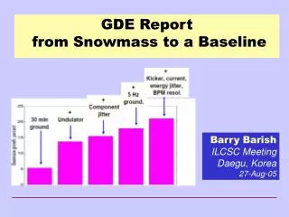
Snowmass Workshop – Aug 2005 Snowmass represents the kickoff of what we all hope will be a successful and truly international process to design and then build the next great particle accelerator !!!
The Mission of the GDE Produce a design for the ILC that includes a detailed design concept, performance assessments, reliable international costing, an industrialization plan , siting analysis, as well as detector concepts and scope. Coordinate worldwide prioritized proposal driven R & D efforts (to demonstrate and improve the performance, reduce the costs, attain the required reliability, etc.) Global Design Effort
Starting Point for the GDE Superconducting RF Main Linac
Ecm adjustable from 200 – 500 GeV Luminosity ∫Ldt = 500 fb-1 in 4 years Ability to scan between 200 and 500 GeV Energy stability and precision below 0.1% Electron polarization of at least 80% The machine must be upgradeable to 1 TeV Parameters for the ILC
Create a baseline configuration for the machine Document a concept for ILC machine with a complete layout, parameters etc. defined by the end of 2005 Make forward looking choices, consistent with attaining performance goals, and understood well enough to do a conceptual design and reliable costing by end of 2006. Technical and cost considerations will be an integral part in making these choices. Baseline will be put under “configuration control,” with a defined process for changes to the baseline. A reference design will be carried out in 2006. I am proposing we use a “parametic” design and costing approach. Technical performance and physics performance will be evaluated for the reference design Design Approach
Proposal-driven R&D in support of the baseline design. Technical developments, demonstration experiments, industrialization, etc. Proposal-driven R&D in support of alternatives to the baseline Proposals for potential improvements to the baseline, resources required, time scale, etc. Develop a prioritized DETECTOR R&D program aimed at technical developments needed to reach combined design performance goals Approach to ILC R&D Program
Schedule Begin - define Configuration (Snowmass Aug 05) Baseline Configuration Document (end of 2005) ----------------------------------------------------------------------- Baseline under Configuration Control (Jan 06) Develop Reference Design (end of 2006) Coordinate the supporting R&D program Three volumes -- 1) Reference Design Report; 2) Shorter glossy version for non-experts and policy makers ; 3) Detector Concept Report GDE – Near Term Plan
2005 2006 2007 2008 2009 2010 Global Design Effort Project LHC Physics Baseline configuration Reference Design The GDE Plan and Schedule Technical Design ILC R&D Program Bids to Host; Site Selection; International Mgmt
Cost Breakdown by Subsystem Civil SCRF Linac
Three concepts under study Typically requires factors of two or so improvements in granularity, resolution, etc. from present generation detectors Focused R&D program required to develop the detectors -- end of 2005 Detector Concepts will be used to determine machine detector interface, simulate performance of reference design vs physics goals next year. Detector Concepts and Challenges
ILCCommunications • Launch New ILC Website • www.linearcollider.org • thanks to Norm Graf for url • “One Stop Shopping” • electronic data management system (EDMS), news, calendar of events, education and communication, • Designer • Xeno Media (Kevin Munday)
Snowmass (Aug 05) first meetings Frascati (Dec 7-10, 2005) (in conjunction with TESLA collaboration meeting) Bangalore, India (March 2006) (in conjunction with LCWS 2006) Our process and meetings will be open! Our website will post all progress, developments, issues and decisions. We invite community input and participation at each step. GDE Process and Meetings
ILC Detector Challenges In order to accomplish our physics goal at ILC With respect to detectors at LHC: • Inner VTX layer 3--6 times closer to IP • VTX pixel size 1 / 30 • VTX materials 1 / 30 • Materials in Tracker 1 / 6 • Track mom. resolution 1 / 10 • EM cal granularity 1 / 200 !!
Jet energy resolution is the key in ILC physics The best jet energy resolution is obtained by reconstructing momenta of individual particles avoiding double counting among Trackers and Calorimeters Charged particles (~60%) measured by Tracker Photons (~30%) by Electromagnetic CAL (ECAL) Neutral hadrons (10%) by ECAL+Hadron CAL (HCAL) Particle Flow Analysis PFA (Particle Flow Algorithm) at the ILC To get good jet energy resolution by PFA: • Separation of particles (reducing the density of charged and neutral particles at CAL surface) is important for PFA : • Fine segmentation of CAL • High B field • Large CAL radius
Design Alternatives Gradient / Length (30MV/m?, 35MV/m? Higher?) Tunnel (single? or double?) Positron Souce (undulator? conventional?) Damping ring (dogbone? small ring?) Crossing angle (head-on, small angle, large angle) Define detailed configuration RF layout Lattice layout Beam delivery system layout Klystron / modulators Cryomodule design Evolve these choices through “change control” process Design Choices for Baseline
The design is intimately tied to the features of the site 1 tunnels or 2 tunnels? Deep or shallow? Laser straight linac or follow earth’s curvature in segments? GDE ILC Design will be done to samples sites in the three regions North American sample site will be near Fermilab Japan and Europe are to determine sample sites by the end of 2005 ILC Siting and Civil Construction
1 vs 2 Tunnels • Tunnel must contain • Linac Cryomodule • RF system • Damping Ring Lines • Save maybe $0.5B • Issues • Maintenance • Safety • Duty Cycle
Recommendation of a Bunch Compressor configuration (1 stage, 2 stage…) Recommendation of a main linac configuration (with WG2, WG5, and GG4) quad spacing cavities per cryomodule quads in RF cryomodules or separate ones straight, bent, or curved tunnel Consider one recommendation for TTC Cavity, and a separate one for low-loss / high-gradient / high wakefield cavity? WG1 – Items to be Completed
Agreement on nominal and “operating plane” beam parameters for LET and IP (with GG1) Agreement on a plan and schedule for completion of work from now until end 2006 Studies for BCD Studies for RDR Development of some “nuts and bolts” standards for exchange of technical information deck formats and repository, etc. WG1 Goals for Snowmass (2)
RF wave-guide distribution Modulators / klystrons Low Level RF Beam interfaces (quadrupoles, BPM’s) Cryomodule Cryo-systems Topics covered by WG2 Important interfaces with other WG’s especially WG5
Focus of Efforts at SLAC Focus of Efforts at JLab and FNAL FNAL-Based SMTF Proposal: “It is anticipated that, with coordination from the ILC-Americas collaboration, SLAC will lead the ILC rf power source efforts ...
Baseline recommendation for cavity is standard TESLA 9-cell Alternatives (energy upgrade): Low-loss, Re-entrant superstructure Gradient
ILC Klystron Development
Baseline Klystrons Specification: 10MW MBK 1.5ms pulse 65% efficiency Thales CPI Toshiba
SMTF at FNAL STF at KEK CMTB at DESY Existing TTF modules remain important means of test (alignment, vibration….). New Cryomodule Test Facilities
1.3 GHz ILC Cryomodule 4 Cavities US Built/purchased 4 Cavities KEK Built/US processed Superconducting Module Test Facility (SMTF) at FNAL Main Goal:Develop U.S. Capabilities in fabricating and operating with Beam Superconducting accelerating cavities and cryomodule in support of the International Linear Collider. High gradient (35 MV/m or Greater) and high Q (~0.5-1e10)
WG3a: ILC Sources: Electrons and Positrons Working Group 3b: Damping Rings
ILC polarized electron source (PES) - possible baseline - DC gun(s) laser room-temperature accelerating sect. standard ILC SCRF modules diagnostics section sub-harmonic bunchers + solenoids • DC gun: • >120 keV HV (TDR) • VHV gun? JLab, Cornell, Nagoya • Laser requirements: • pulse energy: ~ 2 mJ • pulse length: ~ 2 ns • # pulses/train: 2820 • Intensity jitter: < 5 % (rms) • pulse spacing: 337 ns • rep. rate: 5 Hz • wavelength: 750-850 nm • photocathodes: • GaAs/GaAsP • Room temperature linac: • Allows external focusing by solenoids • Same as e+ capture linac
Compton experiment at ATF Polarized e+ Source for ILC
Polarized Positron Production: Compton Scheme: CO2 Version (Omori, et al.)
Undulator source • Uses main electron beam (150-250 GeV) • Coupled operation • Efficient source • Relatively low neutron activation • Polarisation • Laser Compton source • Independent polarised source • Relatively complex source • Multi-laser cavity system required • Damping ring stacking required • Large acceptance ring (for stacking) • Needs R&D • Conventional Source • Single target solution exists • Close to (at?) limits • Independent source WG3a recommendation for baseline Will need ‘keep alive source’ due reliability issues WG3a recommended alternative. Strong R&D programme needed Currently on-hold as a backup solution Positron Source Pre-damping ring notrequired
3km Damping Rings: Three variants 6km 17 km ‘dogbone’
Damping Rings higher Iav smaller circumference (faster kicker) bunch train compression 300km 20km