Download
1 / 1
10 likes | 107 Vues
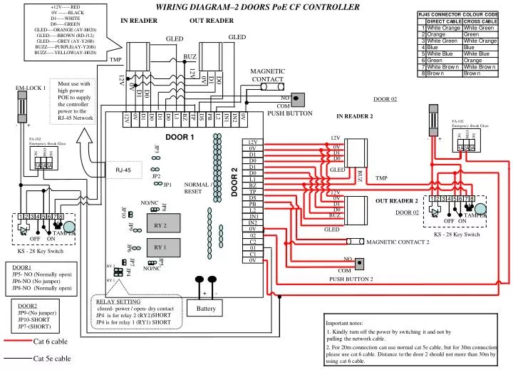
WIRING DIAGRAM–2 DOORS PoE CF CONTROLLER. 12V. 0V. D1. D0. D1. D0. L1. BZ. TP. DS. PB. IN1 . 0V. FA-102 Emergency Break Glass. FA-102 Emergency Break Glass. COM. COM. NC. NO. NO. NC. 1A. 1A. 2A. 2A. 3A. 3A. +12V----- RED 0V ------BLACK D1-----WHITE

E N D
WIRING DIAGRAM–2 DOORS PoE CF CONTROLLER 12V 0V D1 D0 D1 D0 L1 BZ TP DS PB IN1 0V FA-102 Emergency Break Glass FA-102 Emergency Break Glass COM COM NC NO NO NC 1A 1A 2A 2A 3A 3A +12V----- RED 0V ------BLACK D1-----WHITE D0-----GREEN GLED----ORANGE (AY-H020) GLED-----BROWN (RD-J12) GLED-----GREY (AY-Y20B) BUZZ-----PURPLE(AY-Y20B) BUZZ-----YELLOW(AY-H020) IN READER OUT READER GLED GLED BUZ TMP 12V MAGNETIC CONTACT 12V 0V D1 D0 Must use with high power POE to supply the controller power to the RJ-45 Network 0V EM-LOCK 1 D1 D0 DOOR 02 NO COM IN READER 2 12V 0V D1 D0 D1 D0 L1 BZ TP DS PB L2 IN1 IN2 0V - + PUSH BUTTON DOOR 1 12V - + 0V D1 JP3 D0 RJ-45 GLED JP2 TMP BUZ DOOR 2 NORMAL / RESET JP1 12V 0V OUT READER 2 1 2 3 4 5 6 7 8 NO/NC D1 L2 D0 JP8 DOOR 02 BUZ TAMPER IN2 1 2 3 4 5 6 7 8 JP10 OFF ON RY 2 GLED 02 TAMPER KS - 28 Key Switch JP9 C2 OFF ON 01 MAGNETIC CONTACT 2 RY 1 C1 KS - 28 Key Switch JP6 0V NO DOOR1 JP5- NO (Normally open) JP6-NO (No jumper) JP8-NO (Normally open) JP5 NO/NC JP7 RY 2 COM JP4 PUSH BUTTON 2 RY 1 - + RELAY SETTING closed- power / open- dry contact JP4 is for relay 2 (RY2) JP4 is for relay 1 (RY1) SHORT DOOR2 JP9-(No jumper) JP10-SHORT JP7-(SHORT) Battery SHORT Important notes: 1. Kindly turn off the power by switching it and not by pulling the network cable. Cat 6 cable 2. For 20m connection can use normal cat 5e cable, but for 30m connection please use cat 6 cable. Distance to the door 2 should not more than 30m by using cat 6 cable. Cat 5e cable