Download
1 / 1
10 likes | 180 Vues
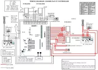
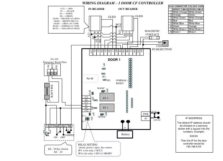
WIRING DIAGRAM – 1 DOOR CF CONTROLLER. FA-102 Emergency Break Glass. COM. NO. NC. 1A. 2A. 3A. +12V----- RED 0V ------BLACK D1-----WHITE D0-----GREEN GLED----ORANGE (AY-H020) GLED-----BROWN (RD-J12) GLED-----GREY (AY-Y20B) BUZZ-----PURPLE(AY-Y20B) BUZZ-----YELLOW(AY-H020).

E N D
WIRING DIAGRAM – 1 DOOR CF CONTROLLER FA-102 Emergency Break Glass COM NO NC 1A 2A 3A +12V----- RED 0V ------BLACK D1-----WHITE D0-----GREEN GLED----ORANGE (AY-H020) GLED-----BROWN (RD-J12) GLED-----GREY (AY-Y20B) BUZZ-----PURPLE(AY-Y20B) BUZZ-----YELLOW(AY-H020) IN READER OUT READER GLED GLED BUZ 12V MAGNETIC CONTACT 12V 0V D1 D0 0V D1 D0 NO COM 12V 0V D1 D0 D1 D0 L1 BZ TP DS PB L2 IN1 IN2 0V PUSH BUTTON DOOR 1 JP3 JP2 RJ-45 NORMAL / RESET JP1 NO/NC EM-LOCK JP8 C2 JP10 02 RY 2 - + C1 JP9 01 0V RY 1 +12 JP6 PWR 14VAC AC JP5 NO/NC JP7 RY 2 IP ADDRRESS The default IP address should be showed on a warranty sticker with a square Into the numbers. Example: XXXXX Then the IP for the door controller would be 192.168.0.XX 230VAC JP4 RY 1 1 2 3 4 5 6 7 8 - + TAMPER Battery ON OFF RELAY SETTING closed- power / open- dry contact JP4 is for relay 2 (RY2) JP4 is for relay 1 (RY11) SHORT KS - 28 Key Switch KS – 20