Download
1 / 27
270 likes | 468 Vues
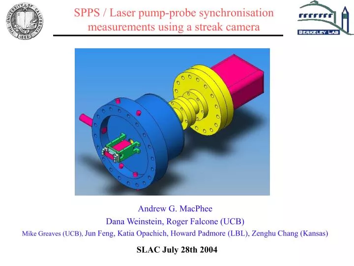
SLAC July 28th 2004. SPPS / Laser pump-probe synchronisation measurements using a streak camera. Andrew G. MacPhee Dana Weinstein, Roger Falcone (UCB) Mike Greaves (UCB), Jun Feng, Katia Opachich, Howard Padmore (LBL), Zenghu Chang (Kansas). Scope of talk.

E N D
SLAC July 28th 2004 SPPS / Laser pump-probe synchronisationmeasurements using a streak camera Andrew G. MacPhee Dana Weinstein, Roger Falcone (UCB) Mike Greaves (UCB),Jun Feng, Katia Opachich, Howard Padmore (LBL), Zenghu Chang (Kansas)
Scope of talk • Fast X-ray streak camera program at UC Berkeley / LBL. • Jitter measurements made at SPPS in January and May with the new camera • Improvement for Mk. III
Challenges for sub-ps regime • The secondary electrons emitted from a photocathode have a finite energy distribution, leading to: • Dispersion of the electrons during transit from photocathode to sweep plates:- degrades temporal resolution. • Chromatic aberration. • For high intensity signals, space charge spreads the electron bunch both parallel to and perpendicular to the propagation direction. • Resolution elements are broadened. • The sweep rate becomes non-linear. • We need: • High extraction field:- to limit dispersion. • Fast sweep:- for small resolution elements. • High electron detection efficiency:- to reduce space charge.
LOW FIELD 7kV, 2mm gap : t ~1.2ps HIGH FIELD 10kV, 0.25mm gap t ~0.110ps Dt 110fs Dt 1.2ps Limits: Dispersion The secondary electron energy distribution of gold and cesium iodide excited by Cu-K radiation at ~8keV has width: E Au: ~3.5eV and E CsI: ~1.7eV We use CsI as the best compromise between energy distribution, moisture tolerance and sensitivity compared to metals and other salts like KBr. Dispersion illustrated with low and high extraction fields: Transit time for electrons between cathode and anode as a function of initial electron energy.
Limits: Space Charge. Parmela simulations Corresponds to ~103 electrons in a 25m diameter spot. At anode exit: ~7m long bunch ~100fs Towards the end of the sweep plates: Pulse stretched to ~1.5ps Corresponds to ~102 electrons in a 25m diameter spot. At anode exit: ~7m long bunch ~100fs Towards the end of the sweep plates: Pulse stretched to ~350fs
2 pulses, 100fs duration, 200fs separation 0.1 SPPS current 0.02 SPPS current
Limits: Cathode saturation • Space charge saturation between cathode and anode: Child-Langmuir law: IV3/2 d-2 • ~80mA (10kV across a 0.25mm gap with a 25m spot) • Corresponds to an incident flux at 8kV of ~5x10⁴ photons in a 100fs pulse. • Certainly possible at LCLS. • But: temporal resolution will have degraded well before this limit. • Saturation of the CsI : • There are ~1011 CsI molecules in a 25micron spot on the cathode (1000Å). • At the space charge saturation limit above there will be ~106 molecules per liberated electron. • This is plenty. • (In the ~ns regime at high flux such saturation effects do occur.)
Limits: • Space charge • Dispersion
Design strategy for a sub 200fs camera • There are five main parts to a streak camera: • Cathode/anode • Electron imaging • Electron detection • Sweep plates • Ramp pulse generator
Design strategy for a sub 200fs camera • Must improve all five components: • Higher extraction field at the cathode: • 10kV across a 0.5mm gap compared to 7kV across a 2mm gap. • Higher spatial resolution: • ~50m compared to ~140m (over a wider field of view) • Higer electron sensitivity: • ~10x. • Less distortion from the sweep plates. • Faster ramp pulse: • ~ 100ps compared to ~300ps • higher switching voltage ±500V compared to ±300V • More robust construction
CsI photo- Cathode. -10kV Magnetic lens Recorded Streak image Back thinned CCD Sweep plates Time Signal from experiment Space Anode (0V) Design strategy: Camera layout
Design strategy: X-ray photocathode / anode assembly • Cathode/anode assembly operates at >10MV/m • within a factor of ~2 of that required for DC operation at ~200fs • For higher fields the cathode must be pulsed. • Initial tests with a 40Hz 10kV pulser (active reverse terminated for a matched transmission line) are promising. • With a 1mm gap, dc emission has been effectively eliminated, whilst the focus appears stable. • Capacitive coupling to the sweep plates introduces movement in the static image. This will be addressed with improved shielding. • The cathode substrates are 1000Å silicon nitride windows on a 400m silicon wafer.
Design strategy: Electron imaging system Lines of equal r×Magnetic vector potential (Gcm2) Measured field on axis: Higher resolution, wider field of view, less field extending in the sweep region
Design strategy: Electron distribution in the image plane for the two camera lenses
Design strategy: Sweep plates • The ramp pulse propagates along the impedance matched microstrip at ~0.7c. • As the electron bunch from the cathode passes each ‘leg’ at ~0.2c, it is influenced by the ramp pulse. • For a linear sweep the electrons must only see the linear part of the ramp at each leg. • The length and geometry of the microstrip and the shape of the ramp pulse is matched to the electron velocity and hence the cathode voltage.
+V -V R R R R +V/2 -V/2 Photoconductive switch Laser pulse Microstrip Sweep plate #1 Microstrip Sweep plate #2 50 50 V/2 0 V -V/2 Bias Flyback { Ramp t Schematic of the +ive and –ive ramp pulses Design strategy: Ramp generator.GaAs photoconductive switch • Within specification for single shot and 1kHz use. • The device is stable at +/–500V bias with a 1kHz, 800nm, ~25J, ~65fs, ~3mm diameter spot falling on a 10 diffuser 2cm from the wafer.
Laser pulse 2400Å SiO2 3000Å Au 400Å Ge 100Å Ni SI GaAs wafer Semi-insulating GaAs Design strategy: Ramp generator Signal switched into a 50 load for a range of applied voltages < 100ps rising edge Damage observed in early switches with no insulation or diffused Ge layer • Germanium/gold alloy electrode contacts • 100Å Ni wetting layer • Rapid anneal at 420C for 30s • Diffusion of germanium into the GaAs
Measured camera performance compared to specification: Static resolution • FWHM ~ 4pixels • 13m pixels → ~50m image • 2× magnification → ~25m resolution at cathode Static CCD image of 25m cathode slot
Measured camera performance compared to specification: Dynamic resolution with UV pulses • Sweep rate: ~60fs/pixel • Linear over full timing window • Dynamic image FWHM ~ 14pixels • ~800fs FWHM typical, ~600fs min
SPPS / Laser Jitter measurement Inherent jitter between SPPS and the laser limits pump probe measurements to ~1ps resolution Online monitoring with the X-ray streak camera provides a timing fiducial for every shot. Full advantage of the ~80fs SPPS pulse can be realised.
10Hz Jitter measurement between SPPS X-ray pulses and the Ti: Sapphire laser phase locked to the SLAC RF signal Laser timing fiducials SPPS X-ray pulse Fit Gaussian to all three pulses: The RMS deviation in the separation of the two laser spots over 1000 shots is ~100fs
Jitter measurements recoded at SPPS in January Autocorrelation: rk = Autocovariance Variance Variance is the average squared departure from the mean. Autocovariance is the average product of departures at times t and t+k 95% Confidence band at ± 2 / N test for randomness Histogram and probability plots of the jitter show an otherwise normal distribution in the correlated data
Comparison between data recorded in January and data recorded in May Histogram and probability plots of the jitter show an otherwise normal distribution in the data. Base width ~3ps, fwhm ~1ps.
Next steps • We have demonstrated reliable jitter measurements at the 100fs level. • We should be able to improve this to ~10fs. • To achieve this we need to improve the dynamic image resolution. • Change sweep mechanism to eliminate distortion. To go any further with streak cameras we will need to: • Eliminate dispersion limitation • Eliminate space charge limitation
New CCD camera for streak camera readout • 12-bit 5kHz real time centroiding on laser and X-ray pulses (binned to two rows) • ~30Hz sustained frame rate with 1400x1400 10micron pixels • Aiming for 120Hz frame rate with 1k x 1k 4 port sensor (25MHz pixel clock) • Useful for 2D X-ray imaging too.