Download
1 / 59
751 likes | 1.4k Vues
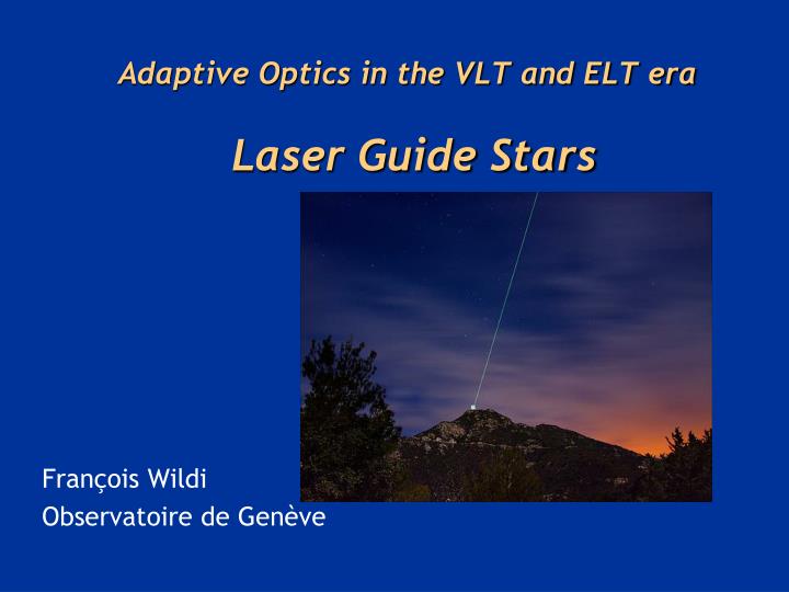
Adaptive Optics in the VLT and ELT era Laser Guide Stars. François Wildi Observatoire de Genève. Outline of this short lecture. Why are laser guide stars needed? Principles of laser scattering in the atmosphere What is the sodium layer? How does it behave?

E N D
Adaptive Optics in the VLT and ELT era Laser Guide Stars François Wildi Observatoire de Genève
Outline of this short lecture • Why are laser guide stars needed? • Principles of laser scattering in the atmosphere • What is the sodium layer? How does it behave? • Physics of sodium atom excitation • Lasers used in astronomical laser guide star AO • Wavefront errors for laser guide star AO
Laser guide stars: Main points of this lecture • Laser guide stars are needed because there aren’t enough bright natural guide stars in the sky • Hence YOUR favorite galaxy probably won’t have a bright enough natural guide star nearby • Solution: make your own guide star • Using lasers • Nothing special about coherent light - could use a flashlight hanging from a “giant high-altitude helicopter” • Size on sky has to be diffraction limit of a WFS sub-aperture • Laser guide stars have PROS and CONS: • Pluses: can put them anywhere, can be bright • Minuses: NGS give better AO performance than LGS even when both are working perfectly. High-powered lasers are tricky to build and work with. Laser safety is added complication.
Two types of laser guide stars in use today: “Rayleigh” and “Sodium” • Sodium guide stars:excite atoms in “sodium layer” at altitude of ~ 95 km • Rayleigh guide stars: Rayleigh scattering from air molecules sends light back into telescope, h ~ 10 km • Higher altitude of sodium layer is closer to sampling the same turbulence that a star from “infinity” passes through ~ 95 km 8-12 km Turbulence Telescope
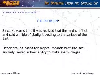
Reasons why laser guide stars can’t do as well as bright natural guide stars 1) Laser light is spread out by turbulence on the way up. • Spot size is finite (0.5 - 2 arc sec) • Can increase measurement error of wavefront sensor • Harder to find centroid if spot is larger 2) For Rayleigh guide stars, some turbulence is above altitude where light is scattered back to telescope. Hence it can’t be measured. 3) For both kinds of guide stars, light coming back to telescope is spherical wave, but light from “real” stars is plane wave • Implications: some of the turbulence around the edges of the pupil isn’t sampled well
Cone effect 90 km “Missing” Data
Scattering: 2 different physical processes • Rayleigh Scattering (Rayleigh beacon) • Elastic scattering from atoms or molecules in atmosphere. Works for broadband light, no change in frequency • Resonance Scattering (Sodium Beacon) • Line radiation is absorbed and emitted with no change in frequency.
Rayleigh Scattering • Due to interactions of the electromagnetic wave from the laser beam with molecules in the atmosphere. • The light’s electromagnetic fields induce dipole moments in the molecules, which then emit radiation at same frequency as the exciting radiation (elastic scattering).
Dependence of Rayleigh scattering on altitude where the scattering occurs • Product of Rayleigh scattering cross section with density of molecules is where P(z) is the pressure in millibars at altitude z, and T(z) is temperature in degrees K at altitude z • Because pressure P(z) falls off exponentially with altitude, Rayleigh beacons are generally limited to altitudes below 8 - 12 km
Rayleigh laser guide stars use timing of laser pulses to detect light from Dz • Use a pulsed laser, preferably at a short wavelength (UV or blue or green) to take advantage of -4 • Cut out scattering from altitudes lower than z by taking advantage of light travel time z/c • Only open shutter of your wavefront sensor when you know that a laser pulse has come from the desired scattering volume Dz at altitude z
Rayleigh laser guide stars • GLAS Rayleigh laser guide star, La Palma. Current. • MMT LGS. current
Sodium Resonance Fluorescence • Resonance scattering occurs when incident laser is tuned to a specific atomic transition. • Absorbed photon raises atom to an excited state. Atom then emits photon of the same wavelength via spontaneous or stimulated emission, returning to the lower state that it started from. • Can lead to large absorption and scattering cross-sections. • Layer in mesosphere ( h ~ 95 km, Dh ~ 10 km) containing alkali metals, sodium (103 - 104 atoms/cm3), potassium, calcium • Strongest laser return is from D2 line of Na at 589 nm.
The atmospheric sodium layer: altitude ~ 95 km , thickness ~ 10 km • Layer of neutral sodium atoms in mesosphere (height ~ 95 km) • Thought to be deposited as smallest meteorites burn up Credit: Clemesha, 1997 Credit: Milonni, LANL
Rayleigh scattering vs. sodium resonance fluorescence Real data: Kumar et al. 2007 • M = molecular mass, n = number density, T = temperature, k = Planck’s constant, g = gravitational acceleration • Rayleigh scattering dominates over sodium fluorescence scattering below h = 75 km. • Atmosphere has ~ exponential density profile:
Image of sodium light taken from telescope very close to main telescope Light from Na layer at ~ 100 km Max. altitude of Rayleigh ~ 35 km Rayleigh scattered light from low altitudes
Overview of sodium physics • Column density of sodium atoms is relatively low • Less than 600 kg in whole Earth’s sodium layer! • When you shine a laser on the sodium layer, the optical depth is only a few percent. Most of the light just keeps on going upwards. • Natural lifetime of D2 transition is short: 16 nsec • Can’t just pour on more laser power, because sodium D2 transition saturates: • Once all the atoms that CAN be in the excited state ARE in the excited state, return signal stops increasing even with more laser power
Sodium abundance varies with season • At University of Illinois: factor of 3 variation between December-January (high) and May-June (low) • In Puerto Rico (Arecibo): smaller seasonal variation. Tropical vs. temperate?
Can see vertical distribution of Na atoms by looking at laser return from side view ~ 105 km ~ 95 km Propagation direction
Time variation of Na density profiles over periods of 4 - 5 hours Night 1: single peaked Night 2: double peaked At La Palma, Canary Islands
Next: discuss line profile of D2 line, and saturation of Na resonance transition • Line profile determines what the linewidth of the laser should be, to get best return signal • Line profile and atomic physics determine “saturation level”: • Beyond a certain incident laser flux, all the atoms that CAN be in the upper state ARE in the upper state. • Laser return signal no longer increases as you increase incident laser power above the power corresponding to saturation.
Doppler Broadening dominates line shape • For gas in equilibrium @ temp. T, fraction of atoms with velocities between v and dv is given by Boltzmann distribution: • For atom moving at velocity v towards source, frequency of the radiation is shifted by: • Rewrite in frequency space as: • HWHM can be found from distribution in frequency space: • For sodium atom at 200 K, Doppler width is ~ 1 GHz: 100 X larger than natural linewidth.
Shape of Doppler-broadened sodium:Na D2 line in mesosphere, T ~ 200 K 12 10 8 6 4 2 ~ 2.5 GHz 0 -1 0 1 2 -2 -3 • 1.8 GHz separation between 2 peaks due to hyperfine splitting of ground state • FWHM ~ 2.5 GHz • Question: if each naturally broadened line is 10 MHz wide (natural linewidth), how many velocity groups are there within FWHM? Answer: ~ 250 velocity groups within the Doppler profile
Result of previous calculation: • If sodium layer is illuminated with a single frequency laser tuned to the peak of the D2 line only a few per cent (of order 10 MHz/1GHz) of the atoms travel in a direction to interact at all with the radiation field. • These atoms interact strongly with the radiation until they collide or change direction. • Use multi-frequency laser in order to excite many velocity groups at once. • Bottom line: Saturation occurs at about Nsat = a few x 1016photons/sec.
CW lasers produce more return/watt than pulsed lasers because of lower peak power • Lower peak power less saturation 3 Keck requirement: 0.3 ph/ms/cm2 3
Laser guide stars: Main points so far • Laser guide stars are needed because there aren’t enough bright natural guide stars in the sky • Hence YOUR favorite galaxy probably won’t have a bright enough natural guide star nearby • Solution: make your own guide star • Using lasers • Nothing special about coherent light - could use a flashlight hanging from a “giant high-altitude helicopter” • Size on sky has to be diffraction limit of a WFS sub-aperture • Rayleigh scattering: from ~10 km, doesn’t sample turbulence as well as resonant scattering from Na layer at ~100 km. But lasers are cheaper and easier to build. • Sodium laser guide stars: must deal with saturation of atomic transition. Means you should minimize peak laser power. Some aspects of optimizing the Na return are not yet understood.
Types of lasers: Outline • Principle of laser action • Lasers used for Rayleigh guide stars • Serious candidates for use with Ground Layer AO • Doubled or tripled Nd:YAG • Excimer lasers • Lasers used for sodium guide stars • Dye lasers (CW and pulsed) • Solid-state lasers (sum-frequency) • Fiber lasers
General comments on guide star lasers • Typical average powers of a few watts to 20 watts • Much more powerful than typical laboratory lasers • Class IV lasers (a laser safety category) • “Significant eye hazards, with potentially devastating and permanent eye damage as a result of direct beam viewing” • “Able to cut or burn skin” • “May ignite combustible materials” • These are big, complex, and can be dangerous. Need a level of safety training not usual at astronomical observatories until now.
Lasers used for Rayleigh guide stars • Rayleigh x-section ~ l-4 short wavelengths better • Commercial lasers are available • Reliable, relatively inexpensive • Examples: • Frequency-doubled or tripled Nd:YAG lasers • Nonlinear crystal doubles the frequency of 1.06 micron light, to yield 532 nm light; quite efficient • Excimer lasers: not so efficient • Example: Univ. of Illinois, l = 351 nm • Excimer stands for excited dimer, a diatomic molecule usually of an inert gas atom and a halide atom, which are bound only when in an excited state.
Current Rayleigh guide star lasers • SOAR: SAM • Frequency tripled Nd:YAG, λ = 355 nm, 8W, 10 kHz rep rate • MMT Upgrade: • Two frequency doubled Nd:YAG, λ = 532 nm, 30 W total, 5 kHz rep rate • William Herschel Telescope: GLAS. Either: • Yb:YAG “disk laser” at λ = 515 nm, 30 W, 5 kHz, or • 25W pulsed frequency-doubled Nd:YLF (or YAG) laser, emitting at λ = 523 (or 532) nm • Both are in the literature. Not sure which was chosen.
Rayleigh guide stars in planning stage • LBT (planned): • Possibly 532nm Nd in hybrid design with lower power Na laser at 589nm • Cartoon courtesy of Sebastian Rabien and Photoshop
Lasers used for sodium guide stars • 589 nm sodium D2 line doesn’t correspond to any common laser materials • So have to be clever: • Use a dye laser (dye can be made to lase at a range of frequencies) • Or use solid-state laser materials and fiddle with their frequencies somehow • Sum-frequency crystals (nonlinear index of refraction)
Dye lasers • Dye can be “pumped” with different sources to lase at variety of wavelengths • Messy liquids, some flammable • Poor energy efficiency • You can build one at home! • Directions on the web • High laser powers require rapid dye circulation, powerful pump lasers
Two types of dye lasers used for sodium laser guide stars • Dye solution is circulated from a large reservoir to the (small) lasing region. Types of lasing region: • Free-space dye jet • Dye flows as a sheet-like stream in open air from a specially-shaped nozzle • Can operate CW (“continuous wave”) - always “on” • Average power limited to a few watts per dye jet • Contained in a glass cell • Dye can be at pressure >> atmospheric • Very rapid dye flow can remove waste heat fast can operate at higher average power
Dye lasers for guide stars • Single-frequency continuous wave (CW): always “on” • Modification of commercial laser concepts • At Subaru (Mauna Kea, HI); PARSEC laser at VLT in Chile • Advantage: avoid saturation of Na layer • Disadvantage: hard to get one laser dye jet to > 3 watts • Pulsed dye laser • Developed for DOE - LLNL laser isotope separation program • Lick Observatory, then Keck Observatory • Advantage: can reach high average power • Disadvantages: potential saturation, less efficient excitation of sodium layer • Efficiency: dye lasers themselves are quite efficient, but their pump lasers are frequently not efficient
Keck dye laser architecture • Dye cells (589 nm) on telescope pumped by frequency doubled Nd:YAG lasers on dome floor • Light transported to telescope by optical fibers • Dye master oscillator, YAG lasers in room on dome floor (Keck) • Main dye laser on telescope • Refractive launch telescope
PARSEC dye laser at the VLT, Chile • Under the Nasmyth platform • More compact than Lick and Keck lasers (I think...)
Solid-State Lasers for Na Guide Stars: Sum frequency mixing concept • Two diode laser pumped Nd:YAG lasers are sum-frequency combined in a non-linear crystal • Advantageous spectral and temporal profile • Potential for high beam quality due to non-linear mixing • Good format for optical pumping with circular polarization • Kibblewhite (U Chicago and Mt Palomar), Telle (Air Force Research Lab), Coherent Technologies Incorporated (for Gemini N and S Observatories and Keck 1 Telescope) (1.06 mm)-1 + (1.32 mm)-1 = (0.589 mm)-1
Air Force Research Lab’s sum-frequency laser is the farthest along, right now • Sum-frequency generation using nonlinear crystal is done inside resonant cavity • Higher intensity, so increased efficiency of nonlinear frequency mixing in crystal • Laser producing 50W of 589 nm light! Telle and Denman, AFRL
Air Force Research Lab laser seems most efficient at producing return from Na layer • Why? • Hillman has theory based on atomic physics: narrow linewidth lasers should work better • Avoid Na atom transitions to states where the atom can’t be excited again • More work needs to be done to confirm theory • Would have big implications for laser pulse format preferred in the future
Future lasers: all-fiber laser (Pennington, LLNL and ESO) • Example of a fiber laser
Potential advantages of fiber lasers • Very compact • Uses commercial parts from telecommunications industry • Efficient: • Pump with laser diodes - high efficiency • Pump fiber all along its length - excellent surface to volume ratio • Disadvantage: has not yet been demonstrated at the required power levels at 589 nm
Laser guide star AO needs to use a faint tip-tilt star to stabilize laser spot on sky from A. Tokovinin
Effective isoplanatic angle for image motion: “isokinetic angle” • Image motion is due to low order modes of turbulence • Measurement is integrated over whole telescope aperture, so only modes with the largest wavelengths contribute (others are averaged out) • Low order modes change more slowly in both time and in angle on the sky • “Isokinetic angle” • Analogue of isoplanatic angle, but for tip-tilt only • Typical values in infrared: of order 1 arc min
Sky coverage is determined by distribution of (faint) tip-tilt stars 1 Galactic latitude = 90° Galactic latitude = 30° 271 degrees of freedom 5 W cw laser 0 • Keck: >18th magnitude From Keck AO book
LGS Hartmann spots are elongated Sodium layer Laser projector Telescope Image of beam as it lights up sodium layer = elongated spot
Elongation in the shape of the LGS Hartmann spots Representative elongated Hartmann spots Off-axis laser projector Keck pupil
Keck: Subapertures farthest from laser launch telescope show laser spot elongation Image: Peter Wizinowich, Keck