Download
1 / 15
150 likes | 298 Vues
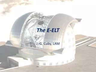
The Adaptive Mirror for the E-ELT. E. Vernet, M. Cayrel , N. Hubin (ESO) R. Biasi , G. Angerer , M. Andrighettoni , D. Pescoller ( Microgate ) D. Gallieni , M. Tintori , M. Mantegazza (ADS) A. Riccardi , M. Riva, G. Pariani , R. Briguglio , M. Xompero (INAF). Outline.

E N D
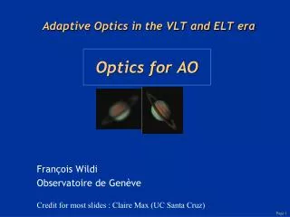
The Adaptive Mirror for the E-ELT E. Vernet, M. Cayrel, N. Hubin (ESO) R. Biasi, G. Angerer, M. Andrighettoni, D. Pescoller (Microgate) D. Gallieni, M. Tintori, M. Mantegazza (ADS) A. Riccardi, M. Riva, G. Pariani, R. Briguglio, M. Xompero (INAF)
Outline • M4 key functional requirements • Positioning system & wavefront correction • AO requirements & additional features • Current design of M4 • Demonstration prototype design & objectives • Project timeline
An adaptive mirror in the E-ELT Main goals: • Provide adaptive correction • Cancel part of telescope wind shaking & static aberrations 10 degree FOV 2 Nasmyth focii In plane centering & tip-tilt system
Positioning system • Decentering capability of +-20 mm (0.5mm accuracy, 0.05 resolution) • Tip-tilt capability of +-2 arcmin (0.5 arcsec accuracy, 0.27 resolution) • Cross-coupling with tilt <54 mas/mm PV lateral displacement • Cross-coupling with lateral displacement 1.85 micron/arcsec PV tilt • 0.5mm position stability in xy & 1 arcsec orientation stability (with LUT), 0.5mm position stability in z (without LUT) Courtesy of Adoptica
Wavefront corrector Correct for both low and high spatial frequencies wavefront errors Stroke budget includes: • Quasi static term(<1Hz) for misalignment errors due to gravity • Term for wavefront errors due to wind load on the telescope structure, M1, M2 (tip, tilt, focus, coma, astigmatism) • Stroke for atmospheric disturbances (15% of total stroke) • Stroke for manufacturing, gravity and thermal effects (35%) TOTAL STROKE BUDGET: 140 micron 50%
AO specifications • Temporal WFE <60nm rms • -3dB Closed loop bandwidth > 400Hz • Segment cophasing
Additional features • Thermal control: • optical surface within [-0.5,+1]ºC • Any other external surface within [-1.5,1.5]ºC • Diagnostics • Maintainability • Safety functions: • Earthquake detection
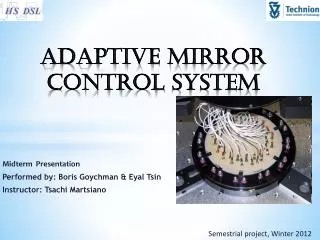
Current design characteristics • 5190 actuators (4326 in pupil) • 6 segment shells ~2mm thick • Light-weighted structural reference body • A “mirror cell” with load spreaders • Hexapod for tip-tilt and decentering • A rotator for Nasmyth selection Courtesy of Adoptica
Shells • Each segment has comparable size as DSM (1 m radial direction, 1.2m on other direction) • Av. thickness tolerance incl wedge :+-15 micron • Local error:10 micron PtV wedge removed • 31.5 mm triangular actuator pattern • Residual optical error after fitting 14nm rms WF (goal 8nm rm WF) • 24 membranes for lateral restraint
Brick concept • Self standing Line Replaceable Unit • Modularity: three types of bricks with respectively 15, 28, 36 actuators • Voice coil motors • Mounting structure + cooling plate for actuators & electronics • Electronics: • Capacitive sensor board • Voice coil driver board • Power + logic on a fin identical for all brick types • Tool for alignment and fixation on the reference body structure Courtesy of Adoptica
Actuators and local sensors • Updated voice coil motor more compact: 36mm long and 15 mm diameter screwed on the cold plate • Same contactless technology but enhanced design for more reliable actuators • New capacitive sensor armature design, signal pick-up strategy and contacting to electronics boards to overcome the problems seen on current units (major source of non working actuators)
Reference body • Triangular structure • ~2500 m diameter • Conical central hole for optical beam clearance • Structure overall thickness 300mm with smaller ribs 100mm thick. • ~ 25mm thick front face • Two materials currently traded-off: Zerodur and SiC • Reference body holds 180 bricks (about 2 kg each) Courtesy of Adoptica
Demonstration Prototype upgrade • 800 mm long, 454mm large • Using same shell as phase B DP • New reference body following M4 design • 10 pre-production bricks 15mm thick with 28 actuators (some partially covered by shells) • Liquefied gas used for cooling • Compliant with real time, control, safety and timing interface requirements Courtesy of Adoptica
DP objectives • Design validation: • Brick concept, • Brick interfaces, • Reference body material, • Control aspects, • Cooling plant design • System performance: • Voice coil actuator design, • Capacitive sensor armature, • Capacitive sensor pick-up, • Shell edge controllability, • Cophasing stability, • Cooling plant efficiency, • Power dissipation, • SW ad HW safety features
Project timeline • DP Reference body material selection: mid September 13 • DP Start of procurement: Oct 13 • Sub-systems assembly readiness review: Dec 13 • DP Electromechanical Testing: late Spring 14 • DP Optical Testing: Summer 14 • Preliminary design review: September 14