Download
1 / 80
820 likes | 1.02k Vues
Polarization of Light: from Basics to Instruments (in less than 100 slides). Originally by N. Manset, CFHT, Modified and expanded by K. Hodapp. Part I: Different polarization states of light. Light as an electromagnetic wave Mathematical and graphical descriptions of polarization

E N D
Polarization of Light:from Basics to Instruments(in less than 100 slides) Originally by N. Manset, CFHT, Modified and expanded by K. Hodapp
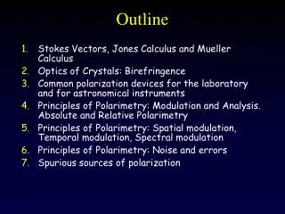
Part I: Different polarization states of light • Light as an electromagnetic wave • Mathematical and graphical descriptions of polarization • Linear, circular, elliptical light • Polarized, unpolarized light Polarization of Light: Basics to Instruments
Part I: Polarization states Light as an electromagnetic wave Light is a transverse wave, an electromagnetic wave ?!? Polarization of Light: Basics to Instruments
Part I: Polarization states Mathematical description of the EM wave Light wave that propagates in the z direction: Polarization of Light: Basics to Instruments
Part I: Polarization states Graphical representation of the EM wave (I) One can go from: to the equation of an ellipse(using trigonometric identities, squaring, adding): Polarization of Light: Basics to Instruments
Part I: Polarization states Graphical representation of the EM wave (II) An ellipse can be represented by 4 quantities: • size of minor axis • size of major axis • orientation (angle) • sense (CW, CCW) Light can be represented by 4 quantities... Polarization of Light: Basics to Instruments
Part I: Polarization states, linear polarization Vertically polarized light If there is no amplitude in x (E0x = 0), there is only one component, in y (vertical). Polarization of Light: Basics to Instruments
Part I: Polarization states, linear polarization Polarization at 45º (I) If there is no phase difference (=0) and E0x = E0y, then Ex = Ey Polarization of Light: Basics to Instruments
Part I: Polarization states, linear polarization Polarization at 45º (II) Polarization of Light: Basics to Instruments
Part I: Polarization states, circular polarization Circular polarization (I) If the phase difference is = 90º and E0x = E0y then: Ex / E0x = cos , Ey / E0y = sin and we get the equation of a circle: Polarization of Light: Basics to Instruments
Part I: Polarization states, circular polarization Circular polarization (II) Polarization of Light: Basics to Instruments
Part I: Polarization states, circular polarization Circular polarization (III) Polarization of Light: Basics to Instruments
Part I: Polarization states, circular polarization... see it now? Circular polarization (IV) Polarization of Light: Basics to Instruments
Part I: Polarization states, elliptical polarization Elliptical polarization • Linear + circular polarization = elliptical polarization Polarization of Light: Basics to Instruments
Part I: Polarization states, unpolarized light Unpolarized light(natural light) Polarization of Light: Basics to Instruments
Part II: Stokes parameters and Mueller matrices • Stokes parameters, Stokes vector • Stokes parameters for linear and circular polarization • Stokes parameters and polarization P • Mueller matrices, Mueller calculus • Jones formalism Polarization of Light: Basics to Instruments
Part II: Stokes parameters Stokes parametersA tiny itsy-bitsy little bit of history... • 1669: Bartholinus discovers double refraction in calcite • 17th – 19th centuries: Huygens, Malus, Brewster, Biot, Fresnel and Arago, Nicol... • 19th century: unsuccessful attempts to describe unpolarized light in terms of amplitudes • 1852: Sir George Gabriel Stokes took a very differentapproachand discovered that polarization can be described in terms of observablesusing an experimental definition Polarization of Light: Basics to Instruments
Part II: Stokes parameters Stokes parameters (I) The polarization ellipse is only valid at a given instant of time (function of time): To get the Stokes parameters, do a time average (integral over time) and a little bit of algebra... Polarization of Light: Basics to Instruments
Part II: Stokes parameters Stokes parameters (II)described in terms of the electric field The 4 Stokes parameters are: Polarization of Light: Basics to Instruments
Part II: Stokes parameters Stokes parameters (III)described in geometrical terms Polarization of Light: Basics to Instruments
Part II: Stokes parameters, Stokes vectors Stokes vector The Stokes parameters can be arranged in a Stokes vector: • Linear polarization • Circular polarization • Fully polarized light • Partially polarized light • Unpolarized light Polarization of Light: Basics to Instruments
Part II: Stokes parameters Pictorial representation of the Stokes parameters Polarization of Light: Basics to Instruments
Part II: Stokes parameters, examples Stokes vectors for linearly polarized light LHP light LVP light +45º light -45º light Polarization of Light: Basics to Instruments
Part II: Stokes parameters, examples Stokes vectors for circularly polarized light RCP light LCP light Polarization of Light: Basics to Instruments
Part II: Stokes parameters (Q,U) to (P,) In the case of linear polarization (V=0): Polarization of Light: Basics to Instruments
Part II: Stokes parameters, Mueller matrices Mueller matrices If light is represented by Stokes vectors, optical components are then described with Mueller matrices: [output light] = [Muller matrix] [input light] Polarization of Light: Basics to Instruments
Part II: Stokes parameters, Mueller matrices Mueller calculus (I) Element 1 Element 2 Element 3 I’= M3M2M1I Polarization of Light: Basics to Instruments
Part II: Stokes parameters, Mueller matrices Mueller calculus (II) Mueller matrix M’ of an optical component with Mueller matrix M rotated by an angle : M’ = R(- ) M R() with: Polarization of Light: Basics to Instruments
Part II: Stokes parameters, Jones formalism, not that important here... Jones formalism Stokes vectors and Mueller matrices cannot describe interference effects. If the phase information is important (radio-astronomy, masers...), one has to use the Jones formalism, with complex vectors and Jones matrices: • Jones vectors to describe the polarization of light: • Jones matrices to represent optical components: BUT: Jones formalism can only deal with 100% polarization... Polarization of Light: Basics to Instruments
Part III: Optical components for polarimetry • Complex index of refraction • Polarizers • Retarders Polarization of Light: Basics to Instruments
Part III: Optical components Complex index of refraction The index of refraction is actually a complex quantity: • real part • optical path length, refraction: speed of light depends on media • birefringence: speed of light also depends on P • imaginary part • absorption, attenuation, extinction: depends on media • dichroism/diattenuation: also depends on P Polarization of Light: Basics to Instruments
Part III: Optical components, polarizers Polarizers Polarizers absorb one component of the polarization but not the other. The input is natural light, the output is polarized light (linear, circular, elliptical). They work by dichroism, birefringence, reflection, or scattering. Polarization of Light: Basics to Instruments
Part III: Optical components, polarizers Wire-grid polarizers (I)[dichroism] • Mainly used in the IR and longer wavelengths • Grid of parallel conducting wires with a spacing comparable to the wavelength of observation • Electric field vector parallel to the wires is attenuated because of currents induced in the wires Polarization of Light: Basics to Instruments
Part III: Optical components, polarizers Wide-grid polarizers (II)[dichroism] Polarization of Light: Basics to Instruments
Part III: Optical components, polarizers Dichroic crystals[dichroism] Dichroic crystals absorb one polarization state over the other one. Example: tourmaline. Polarization of Light: Basics to Instruments
Part III: Optical components, polarizers – Polaroids, like in sunglasses! Polaroids[dichroism] Made by heating and stretching a sheet of PVA laminated to a supporting sheet of cellulose acetate treated with iodine solution (H-type polaroid). Invented in 1928. Polarization of Light: Basics to Instruments
Part III: Optical components, polarizers Crystal polarizers (I)[birefringence] • Optically anisotropic crystals • Mechanical model: • the crystal is anisotropic, which means that the electrons are bound with different ‘springs’ depending on the orientation • different ‘spring constants’ gives different propagation speeds, therefore different indices of refraction, therefore 2 output beams Polarization of Light: Basics to Instruments
isotropic crystal (sodium chloride) anisotropic crystal (calcite) Part III: Optical components, polarizers Crystal polarizers (II)[birefringence] The 2 output beams are polarized (orthogonally). Polarization of Light: Basics to Instruments
Part III: Optical components, polarizers Crystal polarizers (IV)[birefringence] • Crystal polarizers used as: • Beam displacers, • Beam splitters, • Polarizers, • Analyzers, ... • Examples: Nicol prism, Glan-Thomson polarizer, Glan or Glan-Foucault prism, Wollaston prism, Thin-film polarizer, ... Polarization of Light: Basics to Instruments
Part III: Optical components, polarizers Mueller matrices of polarizers (I) • (Ideal) linear polarizer at angle : Polarization of Light: Basics to Instruments
Part III: Optical components, polarizers Mueller matrices of polarizers (II) Linear (±Q) polarizer at 0º: Linear (±U) polarizer at 0º : Circular (±V) polarizer at 0º : Polarization of Light: Basics to Instruments
Part III: Optical components, polarizers Mueller calculus with a polarizer Input light: unpolarized --- output light: polarized Total output intensity: 0.5 I Polarization of Light: Basics to Instruments
Part III: Optical components, retarders Retarders • In retarders, one polarization gets ‘retarded’, or delayed, with respect to the other one. There is a final phase difference between the 2 components of the polarization. Therefore, the polarization is changed. • Most retarders are based on birefringent materials (quartz, mica, polymers) that have different indices of refraction depending on the polarization of the incoming light. Polarization of Light: Basics to Instruments
Part III: Optical components, retarders Half-Wave plate (I) • Retardation of ½ wave or 180º for one of the polarizations. • Used to flip the linear polarization or change the handedness of circular polarization. Polarization of Light: Basics to Instruments
Part III: Optical components, retarders Half-Wave plate (II) Polarization of Light: Basics to Instruments
Part III: Optical components, retarders Quarter-Wave plate (I) • Retardation of ¼ wave or 90º for one of the polarizations • Used to convert linear polarization to elliptical. Polarization of Light: Basics to Instruments
Part III: Optical components, retarders Quarter-Wave plate (II) • Special case: incoming light polarized at 45º with respect to the retarder’s axis • Conversion from linear to circular polarization (vice versa) Polarization of Light: Basics to Instruments
Part III: Optical components, retarders Mueller matrix of retarders (I) • Retarder of retardance and position angle : Polarization of Light: Basics to Instruments
Part III: Optical components, retarders Mueller matrix of retarders (II) • Half-wave oriented at ±45º • Half-wave oriented at 0º or 90º Polarization of Light: Basics to Instruments
Part III: Optical components, retarders Mueller matrix of retarders (III) • Quarter-wave oriented at ±45º • Quarter-wave oriented at 0º Polarization of Light: Basics to Instruments