Download
1 / 1
40 likes | 204 Vues
Fig. 10 WPS system stretched over wiggler magnets at KEKB Oho section. Fig. 6 Alignment reference point and a mirror target. (a). (b). Fig. 3 Variation of angle output. Fig. 2 Variation of R data. Fig. 4 Long term variation of R data. Fig. 5 Long term variation of angle output.

E N D
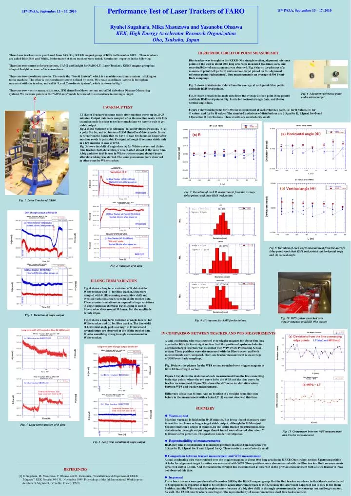
Fig. 10 WPS system stretched over wiggler magnets at KEKB Oho section Fig. 6 Alignment reference point and a mirror target (a) (b) Fig. 3 Variation of angle output Fig. 2 Variation of R data Fig. 4 Long term variation of R data Fig. 5 Long term variation of angle output SUMMARY lWarm-up test Machine warm-up is finished in 20-25 minutes. But it was found that users have to wait for two hours or longer to get stable output, although the IFM output becomes stable in a couple of minutes. In the White tracker measurements, slow deviations in the angle output larger than 0.1mrad were observed after about 7 to 8 hours after power on. This problem is under investigation. lReproducibility of measurements RMS in 5 time measurements of monument positions in about 50m long area was 3.3mm for R, 1.1mrad for F and 1.0mrad for Q. These results are satisfactorily small. l Comparison between tracker measurement and WPS measurement A semi-conducting wire was stretched over the wiggler magnets in about 60m long area in the KEKB Oho straight section. Upstream position of holes for alignment target insertion was measured with WPS. These positions were also measured with the Blue tracker. Both measurements agree well within 0.1mm. And the bend in the straight line measurement as observed in the previous measurement with a Leica tracker [1] was not observed this time. lIn general Three laser trackers were purchased in December 2009 by the KEKB magnet group. But the Red tracker was down in this March and returned to Singapore to be repaired. It had to be sent back again after coming back to KEK because the laser beam happened not to lock to the Home Position. And the White tracker is suspicious now because of a big slow drift in the angle measurement in the warm-up test and long term test As well. The FARO laser trackers look fragile. The reproducibility of measurement in a short time looks excellent. Performance Test of Laser Trackers of FARO Ryuhei Sugahara, Mika Masuzawa and Yasunobu Ohsawa KEK, High Energy Accelerator Research Organization Oho, Tsukuba, Japan 11th IWAA, September 13 – 17, 2010 11th IWAA, September 13 – 17, 2010 III REPRODUCIBILIT OF POINT MEASUREMET Blue tracker was brought in the KEKB Oho straight section, alignment reference points on the wall in about 70m long area were measured five times each, and reproducibility of measurements was observed. Fig. 6 shows the pictures of a monument point (left picture) and a mirror target placed on the alignment reference point (right picture). One measurement is an average of 500 Front- Back samplings. Fig. 7 shows deviations in R data from the average at each point (blue points) and their RMS (red points). Fig. 8 shows deviations in angle data from the average at each point (blue points) and their RMS (red points). Fig. 8(a) is for horizontal angle data, and (b) for vertical angle data. Figure 9 shows histograms for RMS for measurement at each reference point, (a) for R values, (b) for F values, and (c) for Q values. The standard deviations of distributions are 3.3mm for R, 1.1mrad for F and 1.0mrad for Q distributions. These results are satisfactorily small. Three laser trackers were purchased from FARO by KEKB magnet group of KEK in December 2009.These trackers are called Blue, Red and White. Performance of these trackers were tested. Results arereported in the following. There are two control software systems, CAM2 and Insight for FARO LT (Laser Tracker). KEKB magnet group has adopted Insight becauseof its convenience. There are two coordinate systems. The one is the “World System”, which is a machine coordinate systemsticking on to the machine. The other is the coordinate system defined by users. We create coordinate system in level plane measured with the tracker, and call it “Level Coordinate System”, which is shown in Fig.1. There are two ways to measure distance, IFM (InterFeroMeter system) and ADM (Absolute Distance Measuring system). We measure points in the “ADM only” mode because of its convenience in moving a target. Z I WARM-UP TEST LT (Laser Tracker) becomes ready after machine warm-up in 20-25 minutes. Output data were sampled after the machine ready with 1Hz scanning mode in order to see how much time we have to wait to get stable output. Fig.2 shows variation of R (distance) (a) at HP (Home Position), (b) at a point 5m far, and (c) in case of IFM (InterFeroMeter) mode. It can be seen from the figure that we have to wait two hours or longer after machine ready to get stable R output, although it becomes stable only in a few minutes in case of IFM. Fig. 3 shows the drift of angle data (a) for White tracker and (b) for Blue tracker. Both data takings were started almost at the same time. A big and slow drift is seen in White tracker output about 6 hours after data taking was started. The same phenomena were observed in other runs for White tracker. Q Y F X (a) R Fig. 7 Deviation of each R measurement from the average (blue points) and their RMS (red points) Fig. 1 Laser Tracker of FARO Fig. 8 Deviation of each angle measurement from the average (blue points) and their RMS (red points). (a) horizontal angle and (b) vertical angle. II LONG TERM VARIATION Fig. 4 shows a long term variation of R data (a) for White tracker and (b) for Blue tracker. Data were sampled with 0.1Hz scanning mode. Slow drift and eventual variations can be seen in White tracker data. These eventual variations correspond to large variations in angle output as shown in Fig. 5. Jump is seen in Blue tracker data around 30 hours. But the amplitude Is only 20mm. Fig. 5 shows a long term variation of angle data (a) for White tracker and (b) for Blue tracker. The line width of horizontal angle plot is as large as 0.1mrad and several jumps are observed in the White tracker data. It looks something wrong in angle measurement in White tracker. Fig. 9 Histograms for RMS for deviations. IV COMPARISON BETWEEN TRACKER AND WPS MEASUREMENTS A semi-conducting wire was stretched over wiggler magnets for about 60m long area in the KEKB Oho straight section. And the position of upstream holes for alignment target insertion was measured with WPS (Wire Positioning Sensor) system. These positions were also measured with the Blue tracker, and both measurements were compared. Here, one tracker measurement is an average of 500 Front-Back samplings. Fig. 10 shows the picture for the WPS system stretched over wiggler magnets at KEKB Oho straight section. Figure 11(a) shows the deviation of each measurement from the line connecting both edge points, where the red curve is for the WPS and the blue curve for tracker measurement. Figure 9(b) shows the difference in deviation values between WPS and tracker measurements. Difference is less than 0.1mm. And no bending of a straight beam line seen before in the measurement with a Leica LT [1] was not observed this time. Fig. 11 Comparison between WPS measurement and tracker measurement. REFERENCES [1] R. Sugahara, M. Masuzawa, Y. Ohsawa and H. Yamashita, “Installation and Alignment of KEKB Magnets”, KEK Preprint 99-131, November 1999; Proceedings of the 6th International Workshop on Accelerator Alignment, Grenoble, France (1999).