Download
1 / 12
120 likes | 298 Vues
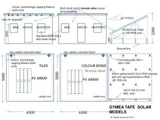
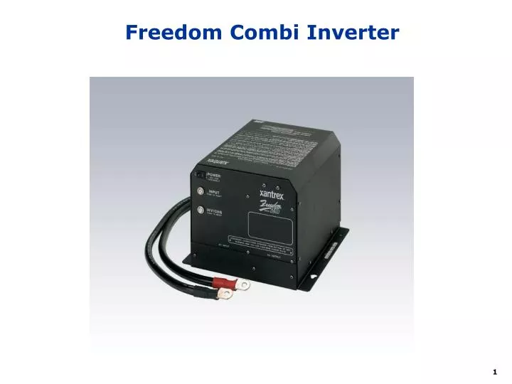
Freedom Combi Inverter. Inverter Power Diagram. Generator. AC1 20A = All Other Inverter Loads AC2 15A = Microwave. 30 Amp Inverter Breaker. 115V AC Input Reset. Main Power Panel. Shore Power. 458 Inverter. 115V. Transfer Switch. AC1. 115V. AC2. 300 A Fuse. Non-Inverter 115V Loads.

E N D
Inverter Power Diagram Generator AC1 20A = All Other Inverter Loads AC2 15A = Microwave 30 Amp Inverter Breaker 115V AC Input Reset Main Power Panel Shore Power 458 Inverter 115V Transfer Switch AC1 115V AC2 300 A Fuse Non-Inverter 115V Loads Charge Invert Aux Start Relay To 12v Loads Thru Disconnect Switch in BCC Chassis Battery BCC
Xantrex 458/(Combi 10) Inverter Charger • Charger – 3 stage temperature controlled • Bulk charge • Constant 100 amps DC charging current (50 amps) • Most of the energy is restored to the battery • Takes 21 amps AC to develop this charge current (11 amps) • Acceptance charge for wet cell batteries • Begins when voltage reaches 14.4v @70deg (Cool) • 90 deg = 14.0 (Warm) • 50 deg = 14.8 • Continues to apply constant voltage until • Charge Current decreases to 15 amps (5 amps) • One hour timer expires • Float charge for wet cell batteries • Maintains voltage of 13.5v @70 deg (Cool) • 90 deg – 13.1 (Warm) • 50 deg = 13.9
458 Multi-Stage Charging • BULK: • Replaces 70-80% of the battery’s capacity at fastest possible rate BULK ACCEPTANCE FLOAT 14.2 volts 100 amps 13.3 volts VOLTAGE Voltage (V) • ACCEPTANCE: • Replenishes remaining 20-30% of battery capacity Current (I) 15 amps or 1 hour • FLOAT: • Charger voltage is held constant. Replaces battery self-discharge and powers other DC loads connected to the battery TIME
Basic Remote Control Can be used with Freedom 458 or Combi Inverters
Combi Remote Control Cannot be used with Freedom 458 Inverters
Reading the Remote - Charging • AC IN - will be lit. • DC AMPS - Drops following the charge cycle. • DC VOLTS - Follows the charge cycle • BATTERY STATE - Indicates stage of charge cycle Left = Bulk, Middle = Acceptance, Right = Float
Reading the Remote - Inverting • AC IN - will NOT be lit. • DC AMPS - Varies with load demand. • DC VOLTS - Drops as battery is consumed • BATTERY STATE - Indicates Approximate Status of batteries. Left = Recharge Needed, Middle = OK, Right = Full
Remote Control Functions • Equalizing Charge –intentional overcharging • Removes sulfate from battery plates • Brings each cell to same voltage and specific gravity • Mixes electrolyte • Wet Cell ONLY • Start with full charge and proper water level • Use Disconnect switch to isolate loads to prevent damage due to high voltage • 16.3 v, variable based on temperature • Timed 8 hour cycle
Power Sharing • Your Charger is an AC load • Uses more power than TV or Microwave • Charging power consumption is variable • Purpose • Sets the maximum limit of power consumption • Benefits • Automatically reduces charger’s consumption • Allows other AC loads on inverter circuit to run • Prevents tripping & overloading of shorepower breaker
Using the Remote - Power Sharing • Check setting every time you hook up • Set to size of your shorepower connection • Default is 30 amps • If breaker trips, reduce setting • Reducing power sharing reduces charger output • But, increases time needed to complete charging
Battery Control Center • Location • In the Electrical Bay • Purpose • Disconnect chassis and coach batteries from their loads • Control ignition switched loads • Controls paralleling of chassis and coach batteries for Charging and Auxiliary Starting • Protects various circuits with fuses and breakers