Download
1 / 23
260 likes | 315 Vues
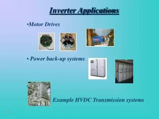
INVERTER. Table of Contents. 1. Loom (textile) control system 2. Loom traverse operation 3. Warper (textile) control 4. Building air-conditioning system using 485 communication 5. Trans parking system 6. Cooling tower system 7. Hoist driving system

E N D
Table of Contents 1. Loom (textile) control system 2. Loom traverse operation 3. Warper (textile) control 4. Building air-conditioning system using 485 communication 5. Trans parking system 6. Cooling tower system 7. Hoist driving system 8. Socks manufacturing system 9. Spray system for humidity control of textile factory 10. Slitting Machine 11. Subway air-conditioning system 12. Apartment water supply system 13. Elevator driving system 14. Aeration tank motor driving 15. Compressor test system 16. Fueling pump driving system 17. Printing machine main motor system 18. Running machine driving system 19. Extruder screw driving system 20. Steel plate line speed control system 21. Coiler driving system 22. Fiber coating system 23. Laboratory air-conditioning system 24. Energy saving case using inverter ------------------ ------------------ ------------------ ------------------ ------------------ ------------------ ------------------ ------------------ ------------------ ------------------ ------------------ ------------------ ------------------ ------------------ ------------------ ------------------ ------------------ ------------------ ------------------ ------------------ ------------------ ------------------ ------------------ ------------------ 1 2 3 4 5 6 7 8 9 10 11 12 13 14 15 16 17 18 19 20 21 22 23 Appendix
Loom (textile) control system 1.Introduction 3.Main function • Driving of yarn drum of loom (textile machine) should be • controlled in line with main motor. Because the conventional • system uses reduction gear, gearing ratio should be changed if • the product type is altered. Therefore, we decided to control • tension using inverter. • -Field : Textile/loom • -Type : iS5 -Linkage control: Speed of main motor that releases the spool should be controlled in line with line speed of the drum. ⇒Rpm of main motor (for spool driving) is used as feedback for main speed control. -PID control: Feedback tension control 2.System construction 4.Others Spool 3-phase A/C Tension sensor SV iS5 M1 M3 Slave INV 5G M2 V1 V2 M2 M4 Main speed, M P/V Motor speed encoder Drum Fixed bar Tension maintaining bar Final product P/V Master INV V1 M1 5G V2 Tension sensor Pulse/voltage converter Textile manufacturer P/V Main speed, M Pulse/current converter Motor speed encoder 1/23
Winder Lint Roving machine Spinning machine Side view Front view Cheese Cheese Drum Drum Guide groove where yarns are wound Clutch Motor (0.4kW) Fixed guide Clutch controller yarn Winder controller Inverter (15kW) Loom traverse operation 1. Introduction 3. Main function • When winding yarns, it is necessary to guide the yarns with traverse. • By traverse operation, the drum’s rpm is altered periodically, so that the yarns do not cluster locally (ribbon effect) or cut off. • Field: Textile machine/loom • Type: SV-iS5 • Traverse operation is performed using traverse function of APP Group, which is characteristic of iS5 • Conventionally, traverse operation was performed using inverter’s up-down operation and FDT function. However, it required additional volume and contact points. 4. Others 2. Process & system construction Parameters for performing traverse operation through external sequence Parameters for iS5 traverse function 2/23
Warper (textile) control 1.Introduction 3.Main function • Winds several strands of yarns in a plane. The inverter • controls winding power and tension power. • - Field: Textile/warper • - Type: SV150iV-4 • - Motor spec: 15㎾,440V.60㎐ -Winder: Winds aligned yarns -Bridle Roll: Applies tension to yarns -Comb-shaped structure: Aligns yarns uniformly 4.Others -In the system construction diagram, the threads consist of more than hundreds (300~600) of yarns. Yarns released from the threads are aligned by the comb-shaped structure and tension is applied to them while they pass the bridle roll. Then, they are wound by the winder after passing the second comb-shaped structure . 2.System construction Yarn spacing maintaining device Winder 5.Operation method -The bridle roll controls back tension with vector inverter. The winder is controlled by “PI” using iS3. Threads Bridle roll for maintaining tension 3/23
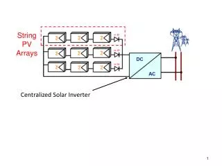
Speed control using RS485 communication INV Flow sensor RA RF N.C Temperature sensor SF CC INV Speed control using RS485 Control Room Building air-conditioning system using 485 communication 1. Introduction 4. System construction • Introduces inverter using ESCO system in order to save energy consumption. • Field: Building air-conditioning/communication • Type: SV-iS5, iH, RS485 option card 10EA 7EA 2. Process construction 13EA 11EA Signal conversion is performed by one “System Base” 485 converter and three “RealSYS” 485converters. Communication between inverters and various thermometers are controlled by the master controller. 5. Others 3. Main function • All 49 inverters are controlled by main control PC in Control Room using RS485 communication. • The inverters are allotted in groups considering communication overload and distance. • Because the user wants constant setup frequency regardless of power on/off,nonvolatile frequency in keypad command region, instead of common region frequency. • The inverter controls air conditioning according to temperature and number of customers, by the command of Control Room. • The supply is turned on, and the flow sensor detects air flow. 4/23
Operation Rotation Passage Inv2 Inv1 PLC Ground level M1 M3 B1 M2 M4 B2 M5 B3 M1 : Main lift M2 : Sub-lift M3,4,5 : For sliding FX RX-ON ON RUN ON ON Brake opening ON ON Fast Lifting Slow Slow Slow Slow Descending Fast Trans parking system 1. Introduction 3. Main function • If the car enters the parking area, it is lifted and placed to its parking position. Because a lot of cars can be parked in small area, this system is suitable for officetels or toll parking lots. • There are upper lifting (end lifting & intermediate lifting) and direct lifting modes according to the position of entrance. • Field: Parking Building • Type : iS5 • Brake opening signal should be output after identifying inverter output. The brake opening signal is generated after identifying operation (or frequency detection) signal in order to prevent falling of cars during inverter breakdown. 2. Process construction • “Dwell” and “DC braking” during startup, and “DC braking” during stoppage help braking. 4. Others • Sufficient flux buildup time is required, because the motor may not be driven if the lifting acceleration time is too fast. • Stall prevention function should not be used when lifting cars. If the stall prevention is activated, the car can fall to the ground accidentally. 5/23
Temperature sensor PID V! Cooling tower system 1.Introduction 3.System construction • -Cooling tower is used to cool down circulation water of • chemical process. Because the cooling method is air-cooling, • fan is required. The fan is driven by motor. • -Conventionally, cooling of circulation water was done in On/OFF • mode. However, we introduced speed control by inverter for • precise control and energy saving. • -Field: Fan/cooling tower • -Type: iH Cooling tower Fan Motor Cooling water Temperature sensing 2.Process construction INV PID controller 4.Main function <PID control> Temperature sensor -Frequency jump: Generally, the cooling tower has two or three resonance points within 0~60㎐. Therefore, operation may happen at resonance points if inverter is used for speed control. In this case, shafts that link motor bearing or motor with fan may be damaged. ⇒When applying frequency jump function, precise resonance points should be identified. For this purpose, speed is gradually altered during installation. Display V! variable resistor <Manual control> 6/23
Hoist driving system 1. Introduction 3. Main function • A system for driving hoist, which is used for repairing lighting towers of baseball park. No precise control is required, but it is required to improve riding comfort. • Field: Hoist/lift • Type: inverter(SV-IS5) • Speed control by voltage • Inverter run output is used for brake signal • Lifting/descent signal is controlled by the rider with lever. 4. Others 2. Process construction Lighting tower • Dynamic Braking resistor is used to prevent release during deceleration. • Acceleration/deceleration time is determined by stop signal and stop position from test operation. DC brake is used to improve riding comfort during brake. • Brake opening signal should be generated by accepting inverter run signal because signal delay or signal error may happen, and it is recommended to equip additional protection equipments such as governor in preparation for inverter error. Rack & pinion ※ Brake operation diagram ~ Brake AXA, AXC Run signals M/C 7/23
Socks manufacturing system 1. Introduction 3. Main function • LG inverter used for main driving source of socks manufacturing machine • Field: Socks manufacturing machine • Type: Inverter (SV-IG5) 1) Inverter - Forward driving startup (FX-CM) - JOG function - Speed control by keypad - Torque increase by manual torque boost function 2. System construction Spool 4. Others - Production speed can be regulated by controlling motor speed with inverter - Because JOG operation is possible, tangled yarns can be disentangled using JOG frequency. - Noise is reduced by inverter operation. - Machine handling becomes easy because machine operating part and inverter can be connected easily. Socks manufacturing Driving force transfer Inverter Motor Final product (socks) 8/23
Factory room sensor Humidity feedback Additional controller Speed control Spray system for humidity control of textile factory 1. Introduction 3. Main function • Humidity control of textile factory is important with regard to product quality. • The humidity control is performed by spraying moisture in room between air path. Generally, this spraying is controlled by valve, but if inverter is used, there will be advantage in control efficiency and energy saving. • Field: Pump • Type: SV-iH • Because the installed valve control system is replaced by motor speed control system, all that is required is matching valve control amount and speed control output. No additional function is required. 2. Process construction 4. Others • If there arises current non-equilibrium at input, this is due to factory electricity supply. It can be solved by adding reactors. 9/23
Slitting Machine 1. Introduction 3. Main function • Slits material of sanitary napkin for women (width: 1 m) in 8 strands and rewinds it. • Field: Linked controller/unwinder, slitting, rewinder, pinch • Type • Unwinder: 037iV-2 1EA • Slitting bridle: 037iV-2 1EA • Rewinder: 022iV-2 4EA • Pinch machine: 037iS3-2 1EA • Maximum line speed is 200m/m, and 10V main speed control is input. • Unwinder: Because minimum diameter of roll is 100 and the gearing ratio is 30:46,40:132,30:24, i.e. 4.048:1, the maximum motor speed is (200/0.1π)(132/40)(46/30)(24/30)=2577rpm. Also, because maximum diameter of the initial material is 1500, motor speed at the maximum line speed becomes (200/1.5π)(132/4046/30)(24/30)=172rpm. That is, 172 ~ 2577 rpm should be maintained at the maximum line speed. • Slitting bridle: Because minimum diameter of roll is 114 and the gearing ratio is 24:44,21:44, i.e. 3.841:1, the maximum motor speed becomes (200/0.1π)(44/21)(44/24)=2145 rpm. • Rewinder : Because minimum diameter of roll is 190 and the gearing ratio is 30:46,1:5, i.e. 7.667:1, the maximum motor speed becomes (200/0.1π)(46/30)(5/1)=2569rpm. And, at the maximum diameter of 1200, the motor speed becomes (200/1.2π)(46/30)(5/1)=407rpm. • The rewinder uses torque minor loop mode in iV winder version. • The unwinder uses iV winder version with variable external PI speed control. The looper position data is linked with front slitting bridle operation. 2. Process Slitting Looper Rewinder Unwinder machine Pneumatic Position Sensor V2 V2 V2 iV037-2 iV022-2 iV037-2 V1 V1 V1 Main Speed Control(0~10V) Main Controller 10/23
에너지 절감 • 설비 유지 보수 용이 • 운전소음 감소 • 물탱크 제거에 따른 설치비용 감소 5. 기타 인 버 터 Subway air-conditioning system 1. Introduction 3. Main function • LG inverter used for air conditioning of subway station • Field: Air conditioner • Type: Inverter (SV-iS5) 1) inverter - Forward driving startup (FX-CM) - Speed control by variable resistor (V1) - Communication control selection using PLC - One-touch control using PMU - Remotely/locally controllable 2. System construction 4. Others Air in Air out - Communication control using PLC and PMU is possible. - System control can be performed in station office because remote/local transition is possible. - Energy consumption is reduced because air supply/return can be controlled by season. - Installation, maintenance and repair are simple. Train Inverter Supply blower Exhaust blower 11/23
Apartment water supply system 1. Introduction 3. Main function • LG inverter used for supplying water to apartment households • Field: Water supply pump for high-rise apartment • Type: Inverter(SV-iS5) 1) Inverter - Forward driving startup (FX-CM) - Speed control by variable resistor(V1) - Control by communication 2) PLC - Process PID control 2. Process construction Apartment (12~18F) 6 buildings / 860 households 4. Others - PLC (Master-k80s) was used as main controller. Speed of 4 inverters was controlled by PID control. - Because the water volume is controlled in real time using inverter, the conventional water tank becomes unnecessary. - Motor noise is reduced remarkably because motor speed is controlled by inverter. - Remote water supply system control is possible using PMU (optional). Pressure gauge PLC 인 버 터 1 인 버 터 2 Inv2 Inv1 Pump 1 Pump 2 Pump 3 Pump 4 인 버 터 3 인 버 터 4 Inv4 Inv3 Underground water tank 12/23
Elevator driving system 1. Introduction 3. Main function • LG vector inverter used for elevator control • Field: Elevator • Type: Inverter(SV-IV5L) 1) Height detection by inverter 2) Acquires optimum speed pattern by calculating remaining distance 3) Position signal is transferred to main controller continuosly 4) Driving signal of electronic brake is directly controlled by inverter 2. Process construction Electronic brake 4. Others Motor Inverter • iV5-L or iV5 can be selected depending on requirements of main controller. • Because the inverter should send and receive specific signal with main controller, matching with the main controller is important.(iV5L Version) • Motor characteristic value is tuned without really driving the motor, by stop-type auto-tuning. Encoder Counter Weight 3Φ AC Sensor Car 13/23
Aeration tank motor driving 1. Introduction 3.Main function • DO(dissolved Oxigen) of water is controlled for rapid reaction • of pollutants and chemicals. • Inverter is used for speed control. • Inverter is used for precise control and energy saving. • Field: Blower/aeration tank • Type: SV075iH-4(75㎾) • Motor spec: 75㎾, 2-pole -PID control is used to precisely control water concentration. 4.Others 2.System construction -Although the blower is energy-saving load, energy consumption is not saved if aeration tank is the main load. ⇒Pressure is applied to the blower of aeration tank because it is positioned in water. Therefore, a large torque is required to overcome the pressure and expel air bubble. Here, the water pressure acts as damper. Blower Damper control and aeration tank characteristics Water concentration detection Power (㎾) Air bubble Inverter PID control General energy-saving characteristic curve Load (blow or flow volume) <Load amount vs. Power consumption> 14/23
Compressor test system 1. Introduction 3. Main function • LG inverter used for compressor test • Field: Screw-type compressor • Type: Inverter(SV-IH) 1) Inverter - Forward driving startup (FX-CM) - Speed control by keypad - Overload trip - Overheat prevention 2. System construction 4. Others Inverter Screw-type compressor • Because frequency can be easily altered with inverter, test can be carried out for any country. • Because the inverter provides data such as power consumption, output voltage and output current, additional equipment is unnecessary. Connected for compressor test Breaker 3-phase output line 3Φ AC 15/23
DCS Control System 4~20mA input 4~20mA P Pressure signal transfer OIL P OIL P OIL P OIL Fueling pump driving system 1. Introduction 3.Main function • -Fueling pump for supplying oil to airplane. Oil pressure is maintained by inverter depending on load change. • Field: Pump • Type: SV-iH -Except for ordinary operation (60㎐) to maintain constant pressure, additional load (fueling amount) is controlled by inverter in order -PID control : 4~20㎃ of pressure signal is transferred to DCS, and DCS sends PID output for inverter control. 2.System construction 4.Others -Because the motor was for medium-voltage (6,600V), UP/DOWN transformer was used to control low voltage inverter (440V). ⇒Inverter input was decreased from 6,600V to 440V. Then, inverter output was increased from 440V to 6,600V because the motor was for 3300V. ⇒Heat resistance is important when selecting the UP/DOWUN transformer, because heat is generated. 16/23
Tension controller 2-Color printing Connected by gear 1-Color printing LG vector inverter 0~10V Variable resistor E Motor Encoder feedback Printing machine main motor driving 1. Introduction 3.Main function • Prints two colors after unwinding paper roll, and then rewinds • it. • -Field: Individual machine (printing machine) • Inverter: SV037iV5-4 (3.7㎾) • Motor spec: 3.7㎾ (Encoder equipped to general motor: • Metronics 1,000Pulse) -ASR (Automatic speed regulator) P,I gain control ⇒P gain: 40% I gain: 400㎳ 2.System construction 4.Others -The rpm variation should be within 1rpm for printing accuracy. ⇒If variation becomes large, printing position may not coincide in 1-color printing and 2-color printing. 17/23
1Φ AC Motor Inverter Running machine driving system 1. Introduction 3. Main function • LG inverter used for controller of running machine driving motor • Field: Running machine • Type: Inverter (SV-IC5) 1) Inverter - Forward driving startup (FX-CM) - Speed change by Up/Down operation - Sensorless vector operation - Motor overheat prevention - Overload trip - Control by communication 2. Process construction 4. Others • Strong torque characteristics at low speed by sensorless • vector • Smooth acceleration/deceleration and reduced noise • Product stability increased by motor overheat prevention • and inverter overload prevention • Communication with running machine specific controller is • possible 18/23
Extruder screw driving system 1. Introduction 3. Main function • LG inverter used for extruder screw driving • Field: Extruder screw • Type: Inverter (SV-IH) 1) Inverter - Forward driving startup (FX-CM) - Speed control by variable resistor (V1) - Motor overheat prevention - Overload trip 2. Process construction Raw material 4. Others - Productivity can be increased because extruder screw speed can be easily controlled by variable resistor (V1). - The screw speed can be controlled in real time depending on the temperature of extruder cylinder. - If the motor is overloaded or overheated because of poor extrusion, the self-protection function protects the motor and inverter without additional equipment. - Because the motor speed is controlled by frequency, the wider and more precise control is possible compared with conventional step control. - Motor noise is reduced. Inverter Screw Motor 19/23
3ΦAC LG vector inverter Cutting roll Steel plate drum Product (steel plate) Leveler Cutter Steel plate Steel plate line speed control system 1. Introduction 3. Main function • LG vector inverter used in steel plate production line • Field: Individual machine (roller) • Type: SV-iV • Forward driving startup (FX-CM) • Up/Down operation • Jog frequency operation • Use DB resistor • Motor overheat prevention • - Overload trip 2. System construction 4. Others • Leveler’s main role is to remove residual stress. • Product size can be controlled precisely by leveler line speed control using inverter. • UP-Down operation and Jog function for ease operation. • Vector was used to precisely control line speed in order to obtain precise dimension of final product. • AC reactance was applied at input line for power-factor improvement and input circuit protection. 20/23
Decelerator Coiler driving system 1. Introduction 3.Main function • -The conventional winding motor requires large current for • startup and is disadvantageous in productivity. • -Inverter is used to reduce startup current and improve • productivity. • -Load: Coiler • -Inverter: SV132iH-4 (132㎾) • -Motor:110㎾ (Modified winding motor) -During startup: Acceleration time should be selected so that the normal speed can be attained within 1min for general 150% load. -During stoppage: Because the rotational inertia is large, free run stoppage and machine brake are used. 2.System construction 4.Others Drum(24inch*6,16inch*9,12inch*1) -Because winding motor is used directly to inverter, internal resistance of the motor was removed. ⇒During wire connection, overheat may damage the wire. Capstan Twister Drum -Twister: Twists 16 strands of wire released from each drum. -Capstan: Applies tension to maintain the twisted state. 21/23