Download
1 / 25
250 likes | 377 Vues
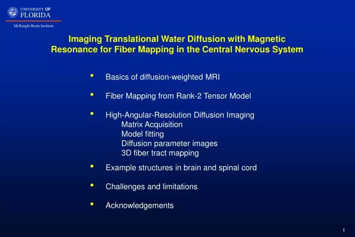
Imaging Translational Water Diffusion with Magnetic Resonance for Fiber Mapping in the Central Nervous System. Basics of diffusion-weighted MRI Fiber Mapping from Rank-2 Tensor Model High-Angular-Resolution Diffusion Imaging Matrix Acquisition Model fitting Diffusion parameter images

E N D
Imaging Translational Water Diffusion with Magnetic Resonance for Fiber Mapping in the Central Nervous System • Basics of diffusion-weighted MRI • Fiber Mapping from Rank-2 Tensor Model • High-Angular-Resolution Diffusion Imaging • Matrix Acquisition • Model fitting • Diffusion parameter images • 3D fiber tract mapping • Example structures in brain and spinal cord • Challenges and limitations • Acknowledgements
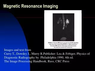
Magnets, Magnetic Resonance, and Imaging Black: Horizontal-solenoid magnet field Gray: Spatial gradients in magnetic field White: Perpendicular rf magnetic field Subject stationary Timing determines contrast
Magnetic Resonance Imaging of 1H in Human Head (THM) at 3 Tesla (128 MHz) Gray Matter (cortex) White Matter (sub-cortex) Cerebral-Spinal Fluid Proton density and T1 weighted Spin echo image acquisition TR 3700 ms, TE 15 ms T2 weighted Spin echo image acquisition TR 3700 ms, TE 90 ms
White Matter and Tissue Structure Axon, ~ 0.2 - 20 mm Microtubules, ~ 0.024 mm Neurofilaments, ~ 0.010 mm x 160,000 EM Waxman, et al., The Axon, Oxford UP, 1995 aS, glial cell aT, axonal cell EM, Bovine optic nerve a) parallel, b) transverse G. Stanisz, A. Szafer, G. Wright, R. M. Hendelman, 1997
Diffusion weighting – b / s mm-2 0 0 4000 8000 12000 16000 -1 Tissue Log (Signal) -2 Water -3 Tissue Microstructure andMR Measures of Water Diffusion Inglis, et al., Magn. Reson. Med. 2001; 45; 580-587Chin, et a, Magn. Reson. Med. 2002; 47; 455-460 Microstructure properties that affect diffusion: • Cell size and density • Cell orientation (anisotropy) • Membrane permeability • Intracellular viscosity • Extracellular viscosity
90° 180° Acquire Rf Gradient D G δ Spin Echo Method for Diffusion Weighted MRI Gradient, G has strength and direction Stejskal-Tanner Equation:
y x z Diffusion-weighting GradientStrength and Orientation Dependence x-gradient diffusion weighting z-gradient diffusion weighting 3 9 15 21 27 G/cm Increasing diffusion weighting
Diffusion Tensor Imaging and Displacement Profiles Basser et al. J. Magn. Reson. B 1994;103: 247-254 Diffusion tensor imaging assumes a rank-2, symmetric, positive-definite tensor model for diffusivities. In this case, the Bloch-Torrey equation for magnetization can be written as, Using a spin-echo measurement method, the diffusion-dependent part of the measured signal, that results from solving this equation, can be written as; Diffusivity in the direction defined by the unit vector , along which the gradient is applied, is given by, Diffusivity in each voxel can be described by an ellipsoidal displacement profile, such as the following, with major and minor axes (eigenvectors).
Anisotropic Diffusion Tensor • Diffusion is highly anisotropic in fibrous structures. • MR is sensitive to the molecular diffusion in the direction of the gradient applied. D, Cartesian tensor for rank 2 • Each voxel is described by a cartesian tensor of rank 2 (32 = 9 elements), but only 6 are unique (real, symmetric matrix), i.e. Diffusion has antipodal symmetry. • Allows measurement of anisotropy • Allows determination of fiber directions. Rank-2 Diffusion tensor image of an excised rat brain at 17.6T (off-diagonal x 10)
Scalar Measures of Diffusion (orientation independent) Basser, NMR Biomed. 1995;8:333-344 Eigenvalues of ; Mean diffusivity; Fractional anisotropy, FA; FA: 0 ~0.5 ~1.0
MR Microscopy of Injured Rat Spinal Cord at 600 MHz (14.1 T, 5.2 cm) SE DWI HARDI acquisition, multiple slice TR=3000ms, TE=27.7ms Δ=17.8ms, δ=2.4ms b = 0, NA 24 b = 1250 s/mm2 in 21 directions, NA 8 FOV 4.8 x 4.8 x 12 mm3 (0.2 mm slices) Matrix 96 x 96 x 60 Resolution 50 x 50 x 200 micron3 Total time, ~ 12 hours So FA <D> Tr(D)color EVcolor Injured excised fixed SD rat spinal cord
Fiber Tract Mapping Algorithm Basser, et al., MRM 2000;44:625-632 Using the principle eigenvector, e1, at all locations in the image to suggest the direction of tracts, a fiber trajectory, , along an arc length, s, may be calculated by solving a Frenet equation, where the tangent vector, , is assumed to the equal to the principle eigenvector along the path, Therefore the Frenet equation can be solved with the initial condition, The trajectory is terminated when the principle eigenvector can no longer be assumed to represents the tract direction (low anisotropy).
Fiber Tract Mapping Implementation a) Specific regions of interest are defined within the three dimensional MR image. b) Starting from these user supplied initial conditions (ROI’s), fiber tracing is initiated in both directions (antipodal symmetry) along the direction defined by the principle eigenvector. c) Then the tract is continued until the anisotropy falls below a pre-specified threshold value (e.g. fractional anisotropy) since it is assumed that fibers do not exist below this level of anisotropy. a) b) c)
Fiber Tracking Results MR Microscopy at 750 MHz (17.6 T, 89 cm) Normal fixed rat brain MR Microscopy at 750 MHz (17.6 T, 89 cm) Normal (L) and injured (R) excised fixed rat spinal cord
A Problem with rank-2 Diffusion-Tensor MRI Rank-2 DT-MRI assumes that there is single fiber orientation within the voxel. Typically voxel size, 100 x 100 x 100 micron3, which in white matter might contain ~ 25 to 125,000,000 axons • What happens when there is directional heterogeneity? • Fiber direction is uncertain • Anisotropy is reduced Idealize Voxel Possible Improvement : High Angular Resolution Diffusion Imaging (HARDI) and modeling with a higher rank Cartesian tensor (>rank 2). Then diffusion measurement can be performed with gradients along many directions making it possible to directly measure distribution of diffusivities. (Tuch et.al., Proc. ISMRM, 1999.)
Extention to Generalized Diffusion Tensor Imaging Ozarslan and Mareci, Magn. Reson. Med 2003;50:955-965 Ozarslan, Vemuri and Mareci, Magn. Reson. Med. 2005;53:866-876 Reformulate DTI by incorporating Cartesian tensors of higher rank Rewrite Bloch-Torrey equation in terms of a rank-l Cartesian tensor: Derive a new expression for signal attenuation:
Diffusion Displacement Probabilities The generalized diffusion tensor defines the rate of diffusion along each direction. Assuming mono-exponential attenuation, the normalized signal can be written as, Therefore, the water displacement probability function is given by the Fourier integral,
Simulation results Generalized Diffusion Tensor Imaging
Effect of Noise on Calculated Voxel Structure Ozarslan, et al., NeuroImage 2006, in press • Simulated system of two crossing fiber bundles. • Probability surfaces calculated using the expansion of the probability on the surface of a sphere. • (c-f) Surfaces in the framed area of panel b recalculated under increasing levels of noise added to the signal values. These panels represent images with signal-to-noise ratios (SNRs) between 50:1 and 12.5:1.
Generalized Diffusion Tensor Imagingof Excised Rat Spinal Cord at 14.1 Tesla (600 MHz) Multiple-slice spin echo acquisition 46 gradient directions, 1 non-weighted image Matrix 72 x 72 x 40, resolution 60 x 60 x 300 mm3 Total acquisition time, 9 hrs, 47 mins
Structures in Optic Chiasm of the Excised Rat Brain Ozarslan, et al., NeuroImage 2006, in press
Calculated Voxel Structures in Excised Rat Brain Ozarslan, et al., NeuroImage 2006, in press
Challenges and Limitations Limitation • MR image measurement • Signal strength • Time for measurement • Motion Challenges • Fiber mapping and probabilistic mapping • Modeling • Optimize data acquisition with modeling • Smoothing • Segmentation • Calculate most probable paths • Relate structure to function • Fiber structure to pathology • Fiber structure to neuronal processing Mark Griswold, Univ. Wurzburg in collaboration with Siemens Medical
Acknowledgements Research Group Sara Berens Neuroscience Min Sig Hwang Biomed Engineering Tom Mareci Biochemistry Evren Ozarslan (now at NIH) Hector Sepulveda Biomed Engineering Nelly Volland Biomed Engineering Collaborators Doug Anderson Neuroscience Steve Blackband Neuroscience Paul Carney Pediatrics Tim Shepherd Neuroscience Baba Vemuri Comp. Info. Sci.& Eng. Bob Yezierski Orthodontics/Neuroscience Grant Support NIH: R01 NS042075 R01 NS004752 P41 RR16105 Dept. of Defense AMRIS Facility Staff Barbara Beck Kelly Jenkins Jim Rocca Dan Plant Xeve Silver Raquel Torres