Download
1 / 21
220 likes | 238 Vues
Calorimeter. 4-May-2009 Added Slides 16-21. 3D Model of Calorimeter. Al tube is modeled with shell elements. Its temperature is set to 90 °K. It is eccentric. Argon. 1.95 mm gap on top. Tungsten Matrix. Copper. Copper Matrix. Copper Matrix. 0.05 mm gap here. Al Tube Eccentricity.

E N D
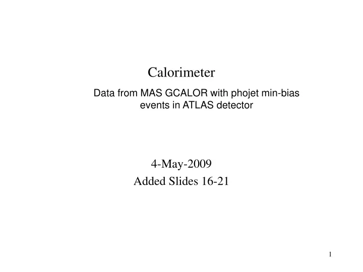
Calorimeter 4-May-2009 Added Slides 16-21
3D Model of Calorimeter Al tube is modeled with shell elements. Its temperature is set to 90°K. It is eccentric. Argon 1.95 mm gap on top Tungsten Matrix Copper Copper Matrix Copper Matrix 0.05 mm gap here
Al Tube Eccentricity Argon Copper matrix
Aluminum Shell and Argon Elements The aluminum shell, above, is wrapped around the OD. It is currently being used as a convenient surface to fix at 90°K. Plate elements are used. They are being plotted here as a surface (no thickness). Liquid argon is modeled with solid conduction elements as shown above. The aluminum shell plates the outer surface.
Conductivities Y Z X
Steady State Temperatures, Argon Excluded This view demonstrates that the OD is held to 90°K
Steady State Temperatures, Argon Jacket Gradient 0.079° K through the 1.95 mm thick argon jacket here 0.012° K through the 0.05 mm thick argon jacket here
Mesh Refinement Checks (2D Models) Baseline Twice Refined Once Refined
Mesh Refinement Checks, Heat Generation A simplified spatial distribution of heat generation is used for these models. Units are W/mm3
Mesh Refinement Checks Baseline Tmax = 90.186 K Once Refined Tmax = 90.185 K Twice Refined Tmax = 90.184 K There is little change in the thermal solution as the mesh is refined. The discretization error is approximately 1.1% These results use a uniform OD gap of 1.95 mm
Comparison of 2D and 3D Results • Using the specified distribution of heat generation in both models: • The 3D model result is: • Max argon temperature 90.147°K • Max metal temperature 90.109°K • The 2 D model result is: • With a uniform 1.95 mm gap at the OD • Max argon temperature 90.188°K • Max metal temperature 90.212°K • With a uniform 1 mm gap at the OD • Max argon temperature 90.129°K • Max metal temperature 90.138°K • These results suggest that in the 3D model heat is being conducted to the bottom of the collimator where the argon gap is small.
Kapton Wrap • The modules are wrapped with 0.1 mm thick Kapton which has about the same conductivity as liquid argon. • The previous results had an 0.05 mm liquid Argon layer at the bottom and a 1.95 mm layer on the top. The minimum layer thickness was increased to 0.1 mm. • Comparing temperatures of a node near the OD at the bottom and top of the copper matrix (Al cylinder deflections are discussed on the following slides): As expected, the thicker insulating area at the bottom increasestemperatures near the bottom by 0.01°C (83%). The temperature near the top increases by 0.002°C (2.5%) meaning that the slightly lower thermal resistance at the top is offset by the doubling of the thermal resistance at the bottom.
Deformation of the Aluminum Cylinder • Up to now the aluminum cylinder has been assumed to be rigid. Its ID is 2 mm larger (1.8 mm accounting for the Kapton wrap) than the module’s OD. The modules were displaced 0.9 mm downward leaving an 0.1 mm gap at the bottom and a 1.9 mm gap on top. • Some deformation of the aluminum cylinder can be expected. To predict this I used a rigid cylinder to represent the modules and added disks to each end of the aluminum cylinder (these keep the ends round). Contact elements were used between the cylinder and modules.
Deformation of the Aluminum Cylinder Rigid Contact Surface (the modules) Nodal forces indicating contact
Clearance Between Modules and Cylinder The cylinder deforms to be closer to the modules from over the region extending to 52° from the bottom. Above 100° the cylinder deforms to move further from the modules than would be the case with a rigid cylinder. The effect on the thermal solution is increased heat transfer (the smaller gap at the bottom outweighs the larger gap at the top. The end of the cylinder is at Z=0 The midpoint is at Z=27.254”
Revised Temperatures, Kapton Wrap and Al Cylinder Deflection