Download
1 / 15
150 likes | 306 Vues
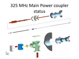
Status of 325MHz coupler. S. Kazakov. 11/29/2011. 325 MHz coupler structure . View of 325 MHZ coupler. View of 325 MHz coupler. Cryomodule flange. 3’’x 0.0315’’ stainless steel tube. Matching bump. Arc detector. Ceramic window. 80K interception. Antenna. Air inlet. Bellows.

E N D
Status of 325MHz coupler S. Kazakov 11/29/2011
Cryomodule flange 3’’x 0.0315’’ stainless steel tube Matching bump Arc detector Ceramic window 80K interception Antenna Air inlet Bellows e-pickup port 5K interception Cold flange 3-1/8’’ coaxial input Spring to compensate thermal expansion
Main sizes of coupler Coupler have been designed to be interchangeable with Khabibuolline-Nicol coupler
Vacuum part of coupler Ceramic window 80K interception 5K interception 0.5’’ copper tube E-pickup port 3’’ x 0.8mm stainless tube Copper tip Bayonet connection
Joints of inner conductor Air holes Thermal isolation Bayonet connection Stainless steel air tube Copper Stainless steel tube Bronze bellows Nut Spring 50 lb
Connection of inner conductor with outer structure Ring with slot Slot. It is possible to place insulator for HV bias Holes for arc detector Arc detector Air inlet
Main electrical parameters of coupler Design CW power ~ 6kW (with air cooling, copper plated vacuum outer conductor, copper-bronze air outer conductor it can sustain several tens kW) Pulse power (breakdown in air) ~ 1MW Multifactor threshold > 6 kW SW (>25kW TW) Passband (S11 < -20dB) ~ 50MHz, (15%)
Thermal properties Dimensions: Pin – input power P_2K, P_5K, P_80K – dissipated powers at 2K, 5K, 80K P_pl – cryo-plant power
Current status: • Design is nearly finished. • Unknown items: • Length of antenna. Coupling value should be chosen and simulated. • Tip shape (depends on test stand cavity design) • Configuration/geometry of 5K, 80K, 300K thermo-interceptors • Configuration of air part outer conductor (coated SS, copper-bronze or uncoated SS)
Next steps: If present design is acceptable (we need approval from community?) , we suppose to make mechanical model to check the method of assembly, antenna air cooling, acoustic vibration of antenna.