Download
1 / 7
70 likes | 87 Vues
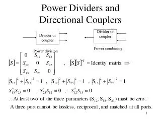
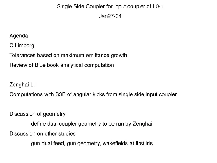
Single Side Coupler for input coupler of L0-1 Jan27-04 Agenda: C.Limborg Tolerances based on maximum emittance growth Review of Blue book analytical computation Zenghai Li Computations with S3P of angular kicks from single side input coupler Discussion of geometry

E N D
Single Side Coupler for input coupler of L0-1 Jan27-04 Agenda: C.Limborg Tolerances based on maximum emittance growth Review of Blue book analytical computation Zenghai Li Computations with S3P of angular kicks from single side input coupler Discussion of geometry define dual coupler geometry to be run by Zenghai Discussion on other studies gun dual feed, gun geometry, wakefields at first iris
Reminder: The 80% emittance is around 0.9 mm.mrad Tolerance : No more than 1-2% growth from Head-Tail & Wakefield effects Linear Head-Tail kick at entrance of L0-1 No Solenoid, No Wakefield With Solenoid, No Wakefield
~2% increase level ~2% increase level First Linac Section Alignment: Wakefield effects • Effects of Wakefields (ignoring ): • Position : 150 m maximum • Angular : 120 rad maximum At end beamline At end beamline
“PHASE TERM” In phase with force Fz Centroid deflection if field on crest “AMPLITUDE TERM” In quadrature with force Fz Strong Head-to-tail effect if field on crest Without cavity offset : With cavity offset : determined from microwave perturbation measurements , but conditions are not described in blue book
Without Cavity Offset Amplitude term dominant (around crest) With Cavity Offset = Amplitude term corrected but not phase term (which becomes dominant beyond +/- 20 degrees off crest)
Conclusions: Tolerance is 120 rad for a 10 ps bunch (due to wakefields along the structure) Without cavity offset , amplitude term is dominant with a 1.2 mrad head-to-tail differential kick when cavity operated around crest With the cavity offset, only amplitude term is corrected. The amplitude of the head-to-tail is now small enough around crest for a 10 ps bunch, however we want to be able to operate : at least +/- 40 degrees off-crest run ~20ps bunch l This result is based on the 0.1% factor measured many years ago (in conditions that we ignore in particular for the field gradient) For all those reasons a numerical computation was needed