Download
1 / 11
110 likes | 254 Vues
MTF analysis for the MODIS-AM. Robert A. Schowengerdt a Francisco Rojas a Stuart F. Biggar b Stuart Marsh c Doug Rautenkranz c a Electrical and Computer Engineering, University of Arizona b Optical Sciences Center, University of Arizona

E N D
MTF analysis for the MODIS-AM Robert A. Schowengerdta Francisco Rojasa Stuart F. Biggarb Stuart Marshc Doug Rautenkranzc a Electrical and Computer Engineering, University of Arizona b Optical Sciences Center, University of Arizona c Office of Arid Lands Studies, University of Arizona
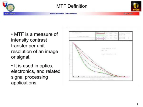
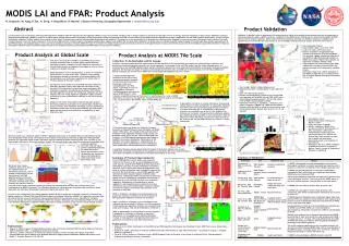
Project summary • Pre-launch MTF • On-orbit MTF • MTF correction and evaluation via NDVI
Pre-launch MTF: fit to data • Detector and integration parameters were available • Optical parameter estimate used IAC pre-launch MTF data • Model fits pre-launch IAC MTF data in cross-track and in-track
On-orbit MTF: inter-sensor comparison: results In-track measured MTF for band 1 (left) and band 2 (right) does not agree with model. Aliasing may be corrupting results?
On-orbit MTF: inter-sensor comparison: results Cross-track measured MTF for band 1 (left) and band 2 (right) appears to agree with model.
MTF correction: ideal and correction • Correct for non-fundamental system components • Cross-track: integration time and optics • In-track: optics Correction filters to bring system MTFs to ideal case Ideal case and system in-track and cross-track MTFs
MTF correction: exampleMaricopa 09/26/2000 MODIS band 1 Before MTF correction After MTF correction MTF correction image difference
Transects for MTF NDVI analysis Maricopa 09/26/2000 T r a n s e c t 3 T r a n s e c t 2 T r a n s e c t 1 N 1 1 / 2 9 / 2 0 0 1
Effect of Spatial Response Correction on NDVI All ETM+ Pixels along Transect Shown ETM+ pixel averaging: Maricopa 9/26/2000 - Transect 1 across 8 columns only 0.500 0.400 0.300 0.200 ETM+ MODIS Uncorrected NDVI MODIS Corrected 0.100 0.000 -0.100 -0.200 Pixel NDVI analysis of transect1
Summary • Pre-launch MTF model and fit to data is good • On-orbit MTF measured by intersensor comparison is good in cross-trackand further analysis needed in-track • MTF correction is promising; continuing analysis and application to VI products
Acknowledgements • MODIS Characterization Science Team (MCST) • MODIS Land Science Support Team • James Storey, Raytheon STX • NASA Grant NAG5-6339