Download
1 / 30
300 likes | 436 Vues
CHIPP Workshop on Neutrino physics. New Readout Methods for LAr detectors. P. Otyugova. ETH Zurich, Telichenphysik. 20.10.2006. Liquid Argon TPCs detect the ionization charge to create the image

E N D
CHIPP Workshop on Neutrino physics New Readout Methods for LAr detectors P. Otyugova ETH Zurich, Telichenphysik 20.10.2006
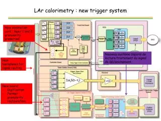
Liquid Argon TPCs detect the ionization charge to create the image of the event and the scintillation light can be used for triggering or T0 definition. To detect the ionization charge in a large noble liquid detector very low noise charge preamplifier is required (challenging, costly). For example: in ICARUS detector the signal is only 15000 electrons for a minimum ionizing particle track with 3mm wire pitch. In this case to obtain a high signal to noise ratio the equivalent noise charge has to be less then 1000 electrons. Signal from a MIP recorded In the Induction plane of T600 ICARUS detector. In 100 kton detector with 20 m drift In a field 1kV/cm the drift time is about 10 ms. With a 2 ms electron lifetime , the 6000 electron/mm signal is attenuated by: It is too low for a readout as in ICARUS (See talk of A.Rubbia)
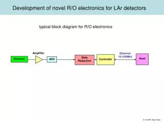
How can we solve this problem? Gas Ar Ampl. + readout Extraction grid race track electrodes e- Liquid Ar References on a Double Phase detection method: Experimental Methods for Particle Dark Matter Detection. Dolgoshein et al., Fiz.El.Chast. Atom. Yad. 4 (1973) 167 To compensate the attenuation and to improve signal-to noise ratio one can introduce a so-called double-phase amplification and readout. In this type of readout the electrons are extracted from the liquid by a grid into the gas phase where they are amplified and read out by a gas multiplier technique. =3mm- the spread from the diffusion on 20m drift distance. It gives a limit on a readout granularity.
Different types of gas avalanche detectors can be proposed for a charge readout: GEM, T-GEM, LEM, MicroMEGAS, ... We are working on the R&D of a Large Electron Multiplier (LEM) made out of standard PCB technique. This method potentially provides a several benefits: 1. Possibility to reach electron amplification gain up to 104. 2. Improvement of signal to noise ratio which results in a possibility to detect events with a lower energy threshold or long drift paths. 3. Low cost and relatively easy mode of operation. For Dark Matter applications, this method potentially provides additional benefits: 1. Improvement of position resolution as compared to PMT readout. 2. Possibility to use very low background materials. 3. Takes less space than PMTs.
What is the LEM? LEM is a thick macroscopic GEM Diameter of the hole: 500 microns. Distance between two holes: 800 microns. LEM thickness: 1.5mm. For HV supply both surfaces are covered with copper electrodes.
For obtaining a necessary gain a double-stage LEM system is required. Multiplication factor (average gain) ~104. The simulation is made for 100% Ar gas at temperature T=87K and pressure1bar.
The detector will consist of 2 LEM stages with 3mm separation Image of the hole is made with magnification x500. Edge of the hole seems to be smooth. It helps us to avoid the corona discharges which can be caused by the sharp and not uniform edges.
Tests of a single-stage LEM at room temperature Experimental setup
The tests • LEMs of 3 different thickness were tested: 2.4mm, 1.6mm, 1.0mm • 2 radioactive sources were used Fe55 (5.8keV X-rays), Cd109 (22keV X-rays) • The tests were made in a pressure range from 1bar to 3.54bar. • The value of the drift field was ~ 100V/cm which according to the simulation provides a 100% transparency for the drifting electrons
Tests of double-stage setup The experimental setup
Double-stage LEM system under construction. Before the tests chamber was evacuated down to a pressure of 2*10-4 mbar. Tests of this setup were performed in a wide range of pressures and temperatures and now it is prepared to be tested in double-phase conditions.
The High Voltage system for the LEM setup The setup is supplied through the voltage divider: R01=R02=100MOhm R11=R12=500MOhm R21=R22=100MOhm
Shapes of the signals from double-stage LEM system on the output of the preamplifier and 50 Ohm input of the oscilloscope. The average signal rise time is about 12s. These are signals from Fe55 radioactive source (5.8 keV), event rate is about 1kHz.
Gain curves at atmospheric pressure and room temperature Transfer field: Etransf=360V/cm
Here you can see a plot which illustrates a shift of gain curves with temperature changes. Nitrogen boiling point: 77K Argon boiling point: 87K
Preparation for the double-phase test To make these tests we have to modify our setup.
The invar-plates levelmeter is used to monitor the liquid level in the setup.
Prototype Stripped LEM readout Here is the schematic view of a LEM prototype with strips. The prototype which we are going to test soon contains 10 strips on each electrode. Strips on both sides of the PCB are perpendicular.
Design of a final LEM readout for ArDM Experiment Number of channels-1024
ARGONTUBE • Full scale measurement of long drift (5 m), signal attenuation and multiplication • Simulate ‘very long’ drift (10-20 m) by reduced E field & LAr purity • High voltage test (up to 500 kV) • Measurement Rayleigh scatt. length and attenuation length vs purity • Design & assembly: • completed: external dewar, detector container • in progress: inner detector, readout system, … Flange with feedthroughs Gas Ar readout grid race tracks e- LAr Extraction from LAr to GAr and LEM readout Extraction from LAr to GAr and LEM readout Field shaping electrodes Field shaping electrodes 8” PMT ET 9357FLA 8” PMT ET 9357FLA
Inner detector design Top view Light pulse source LEM Field shaping rings (10mm spaced) Greinacher chain Bottom view
Outlook Switching to a double-phase technique gives us a possibility to solve a problem of signal-to-noise ratio and signal attenuation in large cryogenic detectors. It is planned to use LEM in many double-phase cryogenic detector projects: ArDM, GLACIER, ARGONTUBE. 3. The preliminary tests showed us, that the multi-stage LEM provides gain of 104 in pure Ar gas at a pressure of 1bar and a temperature of 90K. 4. Gain curves shifts correlated with the temperature changes can be explained with the fact that the gas density increases with decrease of the temperature. 5. For the moment we are already prepared to start a double-phase test of our setup.