Download
1 / 24
250 likes | 499 Vues
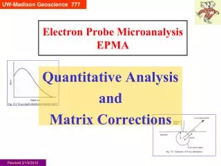
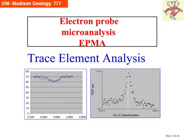
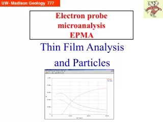
Electron Probe Microanalysis EPMA. Related Topics: Secondary X-ray Fluorescence (XRF) and Synchrotron Radiation. www.powerpointpresentationon.blogspot.com. What’s the point?. We utilize the x-rays produced by the electron microprobe for many research applications.

E N D
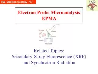
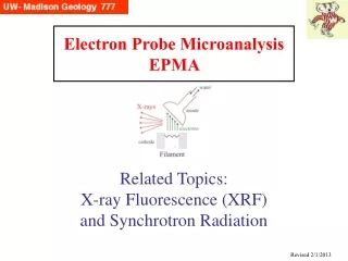
Electron Probe MicroanalysisEPMA Related Topics: Secondary X-ray Fluorescence (XRF) and Synchrotron Radiation www.powerpointpresentationon.blogspot.com
What’s the point? • We utilize the x-rays produced by the electron microprobe for many research applications. • There are other techniques, similar in some ways, that are worth discussing, that utilize x-rays for secondary x-ray fluorescence. Two in particular are: • XRF (X-Ray Fluorescence), where x-rays from a sealed tube are used to produce x-rays by secondary fluorescence in samples of interest (traditionally a macro-technique) • Synchrotron Radiation, where electrons are accelerated in ~10s-100s meters diameter rings, and then made to produce highly focused beams of extremely intense x-rays or light, which are then fed into many different types of experiments. • The benefits of secondary x-ray fluorescence include very low detection limits (10s of ppm easy in 10 seconds, no backgrounds)
XRF Basics • The basics of XRF are very similar to those of EPMA—we are dealing with characteristic x-rays and continuum x-rays— with the exception that we are doing secondary fluorescence : x-ray spectroscopy of our samples using x-rays coming out of a sealed tube to excite the atoms in our specimen. • The big difference is that • there is NO continuum generated in the sample (x-rays can’t generate the Bremsstrahlung), and • we are using BOTH characteristic x-rays of the sealed tube target (e.g., Cr, Cu, Mo, Rh) AND continuum x-rays to generate the characteristic x-rays of the atoms in the sample. • XRF has been a bulk analytical tool (grind up 50-100 grams of your rock or sample to analyze), though recently people are developing “micro XRF” to focus the beam on a ~100 mm spot.
X-ray Sources The standard X-ray tube (top right) was developed by Coolidge (at GE) around 1912. It is desirable to produce the maximum intensity of x-rays; a Cu target tube might be able to deliver 2 kW. The limiting factor is the heat that the target (anode) can handle; cold water is used to remove heat. Higher power can be delivered by dissipating the heat over a larger volume, with a rotating anode (bottom right). However, this is not normally used for XRF. * Power in watts = current [amps] x voltage [volts] From Als-Nielsen and McMorrow, p. 31
characteristic TARGET X-ray (Compton) (Rayleigh) X-ray Attentuation This figure shows the attenuation of the X-rays in the target (sample). In addition to photoelectric absorption (producing characteristic X-rays and photoelectrons [=Auger electrons]), the original X-rays may be scattered. There are two kinds of scattering: coherent (Rayleigh) and incoherent (Compton).
X-ray Scattering Coherent scattering happens when the X-ray collides with an atom and deviates without a loss in energy. An electron in an alternating electromagnetic field (e.g. X-ray photon), will oscillate at the same frequency (in all directions). This is useful for understanding X-ray diffraction (in depth). Incoherent scattering is where the incident X-ray loses some of its energy to the scattering electron. As total momentum is preserved, the wavelength of the scattered photon increases by the equation (in Å) where f is the scatter angle. Since f is near 90°, there will be an addition peak from the main tube characteristic peak at about 0.024Å higher wavelength Coherent Incoherent
Compton Scattering Peaks The top figure shows a wavelength spectrum of the Mo Ka peak from the x-ray tube. The other 3 figures show the splitting of the primary Mo Ka peak into a Compton Scattering Peak due to the incoherent scattering in an Al target, and the effect of changing the scattering angle. From Liebhafsky et al, 1972
Continuum of X-ray Tube in XRF Secondary fluorescence by x-rays in the sample does not produce continuum x-rays there. However, the continuum is produced within the selected x-ray tube which is the “gun” in XRF. This continuum is of interest here as it is useful for excitation source in XRF. Kramers (1923) deduced the relationship between continuum intensity, wavelength and atomic number of the x-ray source (“target”): where the x-ray intensity I is a function of x-ray tube current i, Z is the mean Z of the target and lmin is the E0 equivalent.
Kramers Law and Continuum Intensity • Some comments: • for maximum XRF counts, you want to maximize your current (I) and minimize your lmin which is to say 12.4/E0 …or… run at the highest accelerating voltage your x-ray tube can handle (40-50 keV) • obviously, the higher the Z of the target in the tube, the higher the counts From Williams, Fig 2.2 • finally, Kramers Law is sometimes used in EPMA for theoretically modelling the Bremsstrahlung there
On spectral presentation: XRF Why do these look so different from our “normal” EDS view of a spectrum?????
XRF spectrometer An XRF spectrometer is very similar to an electron microprobe: just replace the electron gun with an x-ray tube located very close to the specimen;both the characteristic and the continuum x-rays cause (secondary) fluorescence of the specimen, and the resulting x-rays are focused using collimators in either WDS (crystal + counter) or EDS (solid state detector) mode . Fig 4-1 Williams
A Currently Marketed XRF (WDS version) This actual model contains additional components. There are probably over a dozen companies building and selling XRFs of various designs. In fact, two are here in Madison: Bruker-AXS (~Siemens) and ThermoNORAN (microXRF) From Bruker-AXS brochure
Sample Prep in XRF Samples and standards (fine powders) are mixed with a flux (e.g., a glass disk with ~90% LiBO4 for major elements, a pressed pellet with ~75% cellulose for traces). The purpose is to minimize “particle size / micro-absorption effects” by producing a more uniform absorption path for samples made of discrete phases that may not have been ground down into submicron sizes.
Correction of XRF Intensity Data • XRF intensity data (counts) is much simplier to correct, compared with EPMA data: • No Z (atomic number) correction • No F (fluorescence) correction • Only A (absorption) correction • Calibration curves are developed for each element.
Synchrotron Radiation (SR) - Defined* Synchrotron = particle (electron, proton, neutron) accelerator. The particle orbits a track; acceleration is produced by an alternating electric field that is in synchronism with orbital frequency. SR = electromagnetic radiation (e.g. radio waves, X-rays) generated within a synchrotron, or through similar natural process in deep space (e.g. some of strongest celestial radio sources). Electrons or other charged particles moving in a strong magnetic field field are forced to spiral around magnetic lines of forces. If they travel near speed of light, they emit, in direction of travel, a sharp beam of electromagnetic radiation polarized normal to the direction of magnetic field. Whether radiation appears as light or radio waves depends on its frequency, which is determined by the electrons’ velocity. * Encyclopedia Britannica, 1974
Synchrotron Setup From Als-Nielsen and McMorrow
Wigglers or Undulators and X-rays Shown here is the cone of x-rays generated by positrons moving with near-speed-of-light energy through an insertion device. The array of permanent magnets produces a magnetic field that alternates up and down along the positron path, causing the particles to bend back and forth along the horizontal plane. At each bend, the positrons emit synchrotron radiation in the x-ray part of the spectrum. From The Advanced Photon Source at Argonne National Laboratory, October 1997 brochure
Synchrotron X-ray Diffraction In x-ray scattering experiments, an x-ray beam is passed through a sample, and the intensities and directions of the scattered x-rays are measured. The pattern of scattered x-rays is converted by the computer into information about the arrangement of atoms in the sample. From The Advanced Photon Source at Argonne National Laboratory, October 1997 brochure
Synchrotron X-ray Microscopy A monochromator and a pinhole are used to select the coherent, laser-like part of an x-ray beam from an APS undulator. This beam is then focused to a tiny spot by a zone plate and directed at a sample being studied. As the sample is scanned back and forth across the beam spot, the x-rays transmitted through the sample are recorded in a computer. The data are then used to develop an image showing the structure of the sample From The Advanced Photon Source at Argonne National Laboratory, October 1997 brochure
Synchrotron X-ray Spectroscopy A beam of x-rays passes through a sample and a measurement is made of the degree to which x-rays of different energies are absorbed by the sample. One type of x-ray spectroscopy is called extended x-ray absorption fine structure, EXAFS. In EXAFS spectra, weak oscillations indicate the effect of scattering from neighboring atoms by an electron ejected from the atom that absorbs an x-ray. This involves electron scattering effects, rather than the x-ray scattering effects described in the previous slide. The weak oscillations in EXAFS spectra can be analyzed by computer models to infer the relative locations of atoms in the structure.
UW-MSN SRC Advances with X-ray source brightness with time From Als-Nielsen and McMorrow
UW-Madison Synchrotron Radiation Center (Stoughton) In 1965 construction began on the 240 MeV electron storage ring Tantalus “for advanced accelerator concepts” tests. But before its completion in 1968, interest in synchrotron radiation research soared, and changes were made to accommodate SR. And it then became dedicated to SR, and here many breakthroughs were made, e.g., the superiority of the electron storage ring as a source of SR was first shown. In 1977, SRC began construction on a new and much larger SR source, Aladdin (1 GeV storage ring). The SRC storage ring beamlines are optimal for ultrahigh vacuum ultraviolet (vuv) and soft x-ray (sxr) research.
UW-Madison SRC • Aladdin was constructed with 36 beam ports, and 4 long straight sections for insertion devices like undulators and wigglers. There are 26 beamlines in operation and 5 under development*. • The SRC serves the requirements for many investigations, including: • high resolution optical absorption spectroscopy of solids and gases • high resolution reflectance spectroscopy of solids • photoinduced luminescence in solids and gases • photoabsorption, dissociation and ionization cross section measurements • chemisorption and physisorption studies • modulation spectroscopy • photoelectron diffraction • x-ray lithography • x-ray microscopy • intrared spectroscopy and microscopy (FT-IR) * 1996 literature quote.
Resources for XRF and Synchrotron Introduction to X-Ray Spectrometry by K. L. Williams, 1987, Allen & Unwin (covers both XRF and EPMA) X-Rays, Electrons, and Analytical Chemistry by Liebhafsky, Pfeiffer, Winslow and Zemany, 1972, Wiley (title says it all) Elements of Modern X-Ray Physics by Als-Nielsen and McMorrow, 2001, Wiley Synchrotron powder diffraction by L.W. Finger, in Modern Powder Diffraction (Bish and Post, eds) Reviews in Mineralogy Vol 20, 1989, Min. Soc. Am.