Download
1 / 35
390 likes | 731 Vues
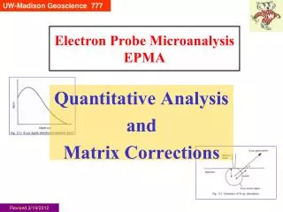
UW- Madison Geoscience 777. Electron Probe Microanalysis EPMA. Electron Optical Column. Updated 2/3/14. UW- Madison Geology 777. What ’ s the point?.

E N D
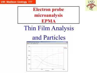
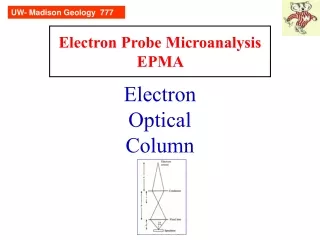
UW- Madison Geoscience 777 Electron Probe MicroanalysisEPMA Electron Optical Column Updated 2/3/14
UW- Madison Geology 777 What’s the point? We need to create a focused column of electrons to impact our specimen, to create the signals we want to measure. This process is identical for both scanning electron microscope (SEM) and electron microprobe (EMP). We use conventional terminology, from light optics, to describe many similar features here.
UW- Madison Geology 777 Key points Source of electrons: various electron guns (thermoionic and field emission). We want high, stable current with small beam diameter. Lenses are used to focus the beam and adjust the current Current regulation and measurement essential Beam can be either fixed (point for quant. analysis) or scanning (for images) Optical microscope essential to position sample (stage) height, Z axis (= X-ray focus) Vacuum system essential
UW- Madison Geology 777 Electron gun Generic EMP/SEM Column/ Electron optics Optical microscope EDS detector Scanning coils SE,BSE detectors WDS spectrometers Vacuum pumps Faraday current measurement
UW- Madison Geology 777 • Two electron sources: thermionic and field emission. • Thermionic – electric current passes thru bent W wire (or sharpened LaB6 crystal tip), heating it and adding thermal energy which permits electrons to overcome the work-function energy barrier of the material– and to leave the wire. A high voltage potential then can “aim” the electrons at nearby anode. Common in electron microprobes and many SEMs. • Field emission – a single crystal, shaped to a very sharp point, and a high voltage potential is placed between it and nearby anode. Two types: cold and hot. Because of the electric field, electrons can jump the energy barrier to the nearby anode. Requires higher vacuum and much more expensive, but has longer life. Common in high resolution SEMs and some newer electron microprobes. Electron Guns
UW- Madison Geology 777 Most common in e-probes and many SEMs is the W filament, a thermionic type. A W wire is heated by ~2 amps of current, emitting electrons at ~2700 K – the thermal energy permits electrons to overcome the work-function energy barrier of the material. $25-$100@ Another thermionic source is LaB6, which has added benefits (“brighter”, smaller beam) but it is more expensive (each tip is 5-10x cost of W filament) and fragile (sensitive to vacuum problems). (Also CeB6). Both have very good (~1%) beam stability, compared the field emission (FE) guns, which are “brighter” and have much smaller beams (great for high resolution SEM images) but lower beam stability and require ultra high vacuum. And for FE, add ~$400K to the price of the SEM or electron probe. Replacement emitter ~$8-12,000@ W and LaB6 sources
UW- Madison Geology 777 For the ultimate in high resolution imaging, FE is tops -- if you have the money. For imaging, you do not need a reliably stable current over minutes-hours-days, as you acquire an image in seconds. However, for quantitative chemical microanalysis (EPMA) you must have a stable current over minutes-hours and hopefully days -- as you must normalize your x-ray counts to beam current. Thermionic vs Field Emission
UW- Madison Geology 777 For the ultimate in high resolution imaging, FE is tops -- if you have the money. Note the importance of reduced beam current (pA not nA)--good for imaging, though not good for EPMA. Side note: beam diameter in electron Resolution Comparison-1 microprobes is incorrectly assumed to be represented by the diameter of the bright CL spot on fluorescent samples. It is not! From Reed
UW- Madison Geology 777 • To right is another version, from a JEOL sales brochure. • I have two comments: • “effective range for analysis by FE is wildly incorrect; no one show believe you can do epma at 100 pA! Normal currents are 10-20 nA • Reed’s figure showing the cross over above 1 nA needs explanation, maybe older cold FE? Resolution Comparison-2 From Reed Above: from JEOL 8530F brochure 2012
UW- Madison Geology 777 Current (~2 A) flows thru the thin W filament, releasing electrons by thermionic emission. There is an HV potential (E0) between the filament (cathode) and the anode below it, e.g. 15 keV. The electrons are focused by the Wehnelt or grid cap, which has a negative potential (~ -400 V), producing the first electron cross over. W filament:biased Wehnelt Cap First electron cross-over Goldstein Fig 2.4, p. 27
UW- Madison Geology 777 Wehnelt diameter (below) is ~20 mm SX50 Gun and Wehnelt
UW- Madison Geology 777 W filament: W filament is ~125 mm diameter wire, bent into hairpin, spotwelded to posts. W has low work function (4.5 eV) and high melting T (3643 K), permitting high working temperature. Accidental overheating will cause quick failure (top right). Under normal usage, the filament will slowly lose W, thinning down to ultimate failure–left, from our SX51. With care/luck, a filament may last 6-9 months, though 1-2 month life is not uncommon. Top 3 images: Goldstein Fig 2.8, p. 33
UW- Madison Geology 777 W filament failure: closeup Recent closeup images of the probe’s W filament, imaged with the Hitachi SEM: note the crystallinity that is accentuated, and the hollowness of the zone where the filament failed.
UW- Madison Geology 777 Brightness is a measure of the current emitted/unit area of source/unit solid area of beam (not used in daily activities) Some electron units/values High voltage and Current - Analogies Baseball HV: speed of the ball curr: size of the ball Water through hose HV: water pressure curr: size of the stream of water
Emission current vs probe (Faraday cup) current This shows filament output on the S3400: emission current IE, which flows from cathode to anode, is high (to 10-4 A). However, what escapes through the hole in the anode and reaches down the column, is much lower, only 10-8 A. Most SEMs can only read IE, lacking Faraday cups.
Saturation on the SX51 “Saturation” is the optimization of 1) current stability (on the plateau) and 2) filament life (minimal heating). The Operating or Saturation point is at the “knee” of the plot. On the SX51, “HEAT” is the variable, with saturation usually between 228 and 200, with new filaments at the upper value, and gradually declining as the filament ages (thins). These are unit-less values (0-255 scale) (left) Goldstein et al Fig 2.5, p. 278
Since >99% of SEMs do not have Faraday cups, they provide “black box” saturation buttons. But that is not optimal for high resolution imaging, where the you need a tight beam. Thus Saturation on the Hitachi S3400 you set the instrument in “filament image” mode and optimize settings to get the tight spot (right), not the “donut” on the left. Goldstein, 2003, p.32
Light Optics Electron Optics UW- Madison Geology 777 Similar geometry to light optics (though inverted: reducing image size): d0 is the demagnified gun (filament) crossover--typically 10-50 um, then after first condenser lens, it is further demagnified to crossover d1. After C2 and objective lens, the final spot is 1 nm-1um. Producing minimum beam diameter (opposite of magnification,here showing the object size shrunk) 1/f = 1/p + 1/q (Goldstein et al, 1992, p. 49) (f = focal distance)
Column: focusing the electrons Simple iron electromagnet: a current through a coil induces a magnetic field, which causes a response in the direction of electrons passing through the field. Rotationally symmetric electron lens: beam electrons are focused, as they are imparted with radial forces by the magnetic field, causing them to curve toward the optic axis and cross it. (Goldstein et al, 1992, p. 44)
UW- Madison Geology 777 Left: shorter working distance (~q2), greater convergence (a2): smaller depth of field, smaller spot (d2), thus higher spatial resolution. Right: longer WD, smaller convergence: larger depth of field, larger spot, decreased resolution. Condenser & Objective Lenses:working distance WD WD Note: we cannot change the working distance on the SX51; however, this is a critical adjustable parameter on the SEM. (Goldstein et al, 1992, p. 51)
UW- Madison Geology 777 Probe current (Faraday cup current, e.g. 20 nA) is adjusted by increasing or decreasing the strength of the condenser lens(es): a) weaker condenser lens gives smaller convergence a1 so more electrons go thru the aperture. Thus higher current with larger probe (d2) and decreased spatial resolution (a2). b) is converse case, for low current situation. Condenser Lenses:adjusting beam current With quant. EPMA we are shooting for high currents, so the left case holds. For SEM work, it depends: for CL and EBSD, the same holds, but for high resolution SE imaging, the right case holds, i.e. drop the current as low as you can get away with. (Goldstein et al, 1992, p. 52)
The electron microprobe and the SEM have significantly different beam diameters and imaging resolutions, because The probe’s main job is cranking out x-ray counts, and to optimize that, you need lots of beam current (tens of nA, up to hundreds for trace elements). Also, because the interaction volume is ~2-3 microns anyway, it makes little sense to worry about “beam size” and “resolution” in EPMA*. But The SEM’s goal is to produce sharp images, and you can utilize several features to do that: (a) Introduce small apertures to tighten up the beam diameter (150, 80, 50, 30 microns) (b) Turn down the probe current (pA) which minimizes scattering (c) Go to high saturation so filament image is tight and centered (d) Go to the shortest working distance possible (e.g. 6 mm) (e) Play with kV, to find best setting (could be high, could be low) Beam Diameter and Imaging Resolution * Exception: now with FE-EPMA, tighter beams and operation at low keV, we do worry!
The electron microprobe and the SEM have significantly different beam diameters and imaging resolutions • The SX51, at its best resolution (set up as SEM, not microprobe), has 70 Å resolution. As set up as a microprobe, its resolution is much worse, maybe ~750 Å; • The S3400, at its best resolution (upon installation/performance tests, using evaporated Gold on Carbon, a common material for such tests) is rated at: • Secondary electron image at 30 kV: 30 Å • Secondary electron image at 10 kV: 100 Å • Backscattered electron image at 30 kV: 40 Å Beam/Probe Diameter and Imaging Resolution
One common SEM resolution is defined as “point to point” resolution and is the smallest separation of adjacent particles that can be detected in an image. The manufacturers “cheat” by using optimal images, sputtered gold balls on carbon (image to right), where there is good secondary electron generation and high contrast. It is optimized in being a 3D image where the Resolution Tests secondary electrons show surface well. A flat polished rock thin section would not show such fine scale resolution. Also note that a 3 nm (30 A) resolution does not mean you can see 3 nm gold balls: most of the balls are ~50 nm in size. Another resolution test is scanning across a very sharp edge (e.g. razor blade) and determining the distance between 85-90% to 15-10% of the intensity drops off.
UW- Madison Geology 777 EPMA requires precise measurement of X-ray counts. X-ray count intensity is a function of many things, but here we focus on electron dosage. If we get 100 counts for 10 nA of probe (or beam or Faraday) current, then we get 200 counts for 20 nA, etc. Therefore, it is essential that we 1) measure precisely the electron dosage for each and every measurement, and 2) attempt to minimize any drift in electron dosage over the period of our analytical session. The first relates to monitoring, the second to beam regulation. Probe current: monitoring and stabilization
UW- Madison Geology 777 Electron beam intensity must be measured, to be able to relate each measurement to those before and after (i.e. to the standards and other unknowns). This is done with a Faraday cup, where the beam is focused tightly within the center of a small aperture over a drilled out piece of graphite (or metal painted with carbon). Current flowing out is measured. Probe current monitoring Why graphite? Because it absorbs almost all of the incident electrons, with no backscattered electrons lost. Goldstein et al 1992, Fig 2.25, p. 65
UW- Madison Geology 777 Modern electron microprobes have built in, automatic, Faraday cups. This is a small cup that sits just outside of the central axis of the column, and can be swung in to intercept the beam upon automated control. This is typically done at the end of each measurement on both standards and unknowns, and using these values, the measured X-ray counts are normalized to a nominal value (e.g. 1 nA, or actual nominal value like 20 nA) In older instruments, this automation was not implemented. An alternative solution would be to create a homemade Faraday cup and mount it with samples, and move the stage to it to do the measurement, or measure absorbed current on another reference material (e.g. brass). Probe current monitoring Goldstein et al 1992, Fig 2.25, p. 65
UW- Madison Geology 777 Optimally, the beam current should remain as constant as possible, particularly over the duration of each measurement (depends upon number of elements, etc, but most are 45-120 seconds). This is accomplished in a feedback loop with the condenser lenses, where a beam regulation aperture measures the electrons captured on a well defined area (red area on bottom aperture), where larger Probe current regulation aperture above it provides ‘shading’ and eliminates ‘excess’ electrons (green). Reed 1993, Fig 4.12, p. 47
UW- Madison Geology 777 The primary mission of the electron microprobe is to focus the beam on a spot and measure X-rays there. However, it was early recognized that being able to scan (deflect) the beam had two advantages: X-rays could be produced without moving the stage, and electron images could be used to both identify spots for quantification, and for documentation (e.g. BSE images of multiphase samples). Later, with the development of the SEM as a separate tool, scanning was essential. Scanning Coils Scanning requires 1) deflection coils and 2) display system (CRT) with preferably 3) digital capture ability. Reed 1993, Fig 2.3, p. 18
UW- Madison Geology 777 The electron probe, a fine point (<1 um) is rapidly scanned across the sample, and the signal from each (x,y) coordinate is mapped onto the screen or a file. Scanning --> 2 D Image Goldstein et al, 3rd Edition, Fig 4.4
UW- Madison Geology 777 Fixed Working Distance SX50/1 specs Rowland Circle Radius Optical Microscope Mag
UW- Madison Geology 777 An essential part of an electron microprobe is an optical microscope. The reason is that we need to consistently verify that all standards and specimens sit at the precise same height (Z position). This is because they must all be in “X-ray spectrometer focus”, which shortly you will find described as the “Rowland circle”. Mounting of specimens relative to an absolute height is problematic, for a variety of reasons (difficult to mount samples perfectly flat, and the fact that we use different holders and shuttles manufactured to different tolerances, together with different screw tightenings by operators.) Optical Microscope
UW- Madison Geology 777 Go to Vacuum Module