Download
1 / 47
470 likes | 473 Vues
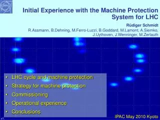
Machine Protection Systems. J örg Wenninger CERN Beams Department Operations group Special CERN CAS, Feb. 2009. Introduction Beam induced damage CERN accelerators risks Beam dumps Passive protection Failure studies & outcome. Introduction. Safety at Accelerators.

E N D
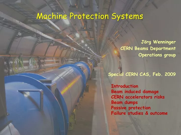
Machine Protection Systems JörgWenninger CERN Beams Department Operations group Special CERN CAS, Feb. 2009 Introduction Beam induced damage CERN accelerators risks Beam dumps Passive protection Failure studies & outcome
Introduction CERN CAS - J. Wenninger
Safety at Accelerators • Accelerators, as all other technical systems, must respect some general principles with respect to safety: • Protect the people (legal requirements). • Protect the environment (legal requirements). • Protect the equipment: • – Without beam : superconducting magnets, high power equipment, power cables, normal conducting magnets, RF systems, etc. • – With beam: damage caused by beams. This presentation on “Machine Protection” is focused on equipment protection from damage caused by beams. CERN CAS - J. Wenninger
Trends in modern accelerators • All major accelerator projects are push to new records: • the beam energy, • Hadron colliders – LHC. • Linear e+e- colliders. • the power and the brightness, • Beam power itself. • Photon beam brightness (synchrotron light sources). • >> in both cases the energy (density) stored in the beams increases ! In many projects machine protection aspects have a large impact on (or may even dominate) design and operation. CERN CAS - J. Wenninger
Modern accelerators require protection systems • High power accelerators : from some 10 kW to above 1 MW. • Neutron spallation sources (SNS, ISIS). • High power/high duty cycle machines (PSI cyclotron, JPARC). • High energy hadron colliders and synchrotrons. • TEVATRON, HERA, LHC. • Synchrotrons for fixed target experiments (SPS). • Synchrotron light sources. • High power photon beams. • Linear colliders/XFELs – single pulses may lead to damage • SLAC linac, ILC, CLIC, NLC and FLASH. • Energy recovery linacs. • Medical accelerators. • The patients ! CERN CAS - J. Wenninger
Risks and protection • Protection is required since there is some risk. • Risk = probability of an accident • xconsequences (in Euro, downtime, radiation doses). • Probability of an uncontrolled beam loss: • What are the failures that lead to beam loss into equipment? • What is the probability for the most likely failure modes? • Consequences: • Damage to equipment. • Downtime of the accelerator for repair. • Activation of material, dose to personnel. • >> The higher the risk, the more protection becomes important ! CERN CAS - J. Wenninger
Beam loss in materials • Particle losses lead to particle cascades in materials • the maximum energy deposition can be deep in the material at the maximum of the hadron / electromagnetic shower. • particle showers from hadrons with energies of 100’s of GeV to some TeV have a penetration depth of some meters. • The energy deposition leads to a temperature increase, and for very fast losses to shock waves and to plastic deformation. • material can melt, vaporize, deform or lose its mechanical properties. • limited risk for some 10 kJ, large risk for some MJ. • equipment becomes activated due to beam losses (acceptable is ~1 W/m and As Low As Reasonably Achievable -ALARA). • superconducting magnets can quench (become normal-conducting). • … CERN CAS - J. Wenninger
Relevant parameters for MPS • Momentum of the particle • Particle type • Activation is mainly an issue for hadron accelerators. • Energy stored in the beam • 1 MJ can heat and melt 1.5 kg of copper. • 1 MJ = energy stored in 0.25 kg of TNT. • Beam power • Beam size • Power or energy density • Time structure of beam The energy of a 200 m long train at 155 km/hour corresponds to the energy of 360 MJoule stored in one LHC beam For synchrotron light sources, ‘beam’ refers both to the primary e-/e+ beam and to the synchrotron light photon beam ! CERN CAS - J. Wenninger
3P’s of a modern Machine Protection System • Protect the machine • Highest priority is to avoid damage of the accelerator. • Protect the beam • Complex protection systems reduce the availability of the accelerator. • One must minimize the number of “false” interlocks stopping operation. • Trade-off between protection and operation. • Provide the evidence • Clear diagnostics must be provided when: • the protection systems stop operation, • something goes wrong (failure, damage, but also ‘near miss’). CERN CAS - J. Wenninger
MPS conceptual architecture Interlock System Abort system User interlock signals • Actors and signal exchange for the MPS system: • User systems survey equipment or beam parameters, are able to detect failures and send a signal to the interlock system. • The interlock system combines the signals and communicates with the abort system. • An abort actionis executed by the abort system when an interlock is detected : • Beam dump. • Injection stop. • Source stop. • … CERN CAS - J. Wenninger
Failure classification • Type of the failure: • Hardware failure (power converter trip, magnet quench, AC distribution failure, object in vacuum chamber, vacuum leak, RF trip, .…). • Controls failure (wrong data, wrong magnet current function, trigger problem, timing system, feedback failure, ..). • Operational failure (chromaticity / tune / orbit errors, …). • Beam instability (high beam / bunch current). • Parameters for the failure: • damage potential. • probability for the failure. • time constant for beam loss. • Machine state when failure occurs: • beam transfer, injection and extraction (single pass). • stored beam. CERN CAS - J. Wenninger
Passive and active protection • Passive protection • Collimators. • Masks. • Absorbers. • Dumps. • Obstacles to absorb the energy • Active protection • High reliability designs (minimize failure occurrence). • Equipment surveillance. • Beam observation. • Detection of a failure directly on the equipment or by its effects on the beam. Modern MP systems usually require both passive and active protection to cover all failure cases. CERN CAS - J. Wenninger
Failure time scales – circular machines • Single turn (single-passage) beam loss (ns -μs) • Failures of kicker magnets (injection, extraction kicker magnets). • Transfer failures between two accelerators or from an accelerator to a target station. High reliability design Passive protection • Very fast beam loss (μs - ms) • Multi turn beam losses in circular accelerators. • Large variety of possible failures, mostly in the magnet powering system, with a typical time constant of some 10 turns to many seconds • Fast beam loss (some 10 ms to seconds) • Slow beam loss (many seconds) Active protection CERN CAS - J. Wenninger
Design principles • Failsafe design. • Internal fault detection. • Frequent and systematic testing. • Redundancy of critical equipment. • Critical processes performed by hardware and not by software. • No remote changes of most critical parameters • Demonstration of safety, availability and reliability. • Use of established methods to analyze critical systems and to predict failure rate. • Management and tracking. • Proper management and tracking of modifications. CERN CAS - J. Wenninger
Beam induced damage CERN CAS - J. Wenninger
108 plates 30 cm 6 cm 6 cm Beam induced damage test The effect of a high intensity beam impacting on equipment is not easy to evaluate, in particular when you are looking for damage: heating, melting, vaporization, shock waves… >> very little experimental data available ! • >> Controlled beam experiment for the LHC: • Special target (sandwich of Tin, Steel, Copper plates) installed in an SPS transfer line. • Impact of 450 GeV beam. Dump Screen Ti entrance window CERN CAS - J. Wenninger
Damage potential of high energy beams • Controlled experiment with 450 GeV beam to benchmark simulations: • Melting point of Copper is reached for an impact of 2.5×10¹² p, damage at 5×10¹² p. • Stainless steel is not damaged with 7×10¹² p. • Results agree with simulation. • Effect of beam impact depends strongly on impact angles, beam size… A B D C Based on those results the LHC has a limit for ‘safe beam’ at 450 GeV of 1012 protons ~ 70 kJ ~ 0.3% of the total intensity Scaling the results (beam size reduction etc) yields a limit at 7 TeVof 1010 protons ~ 12 kJ ~ 0.003% of the total intensity CERN CAS - J. Wenninger
Uncontrolled damage tests… • Here an example from SPS run in 2008 ! • The effect of an impact on the vacuum chamber of a 400 GeV beam of 3x10¹³ p (2 MJ). • Vacuum chamber to atmospheric pressure, Downtime ~ 3 days. CERN CAS - J. Wenninger
vaporisation melting Simulation : full LHC beam deflected into copper target Copper target 2808 bunches 2 m Energy density [GeV/cm3] on target axis The beam will drill a hole along the target axis !! Target length [cm] CERN CAS - J. Wenninger
CERN accelerators on the MPS risk scale CERN CAS - J. Wenninger
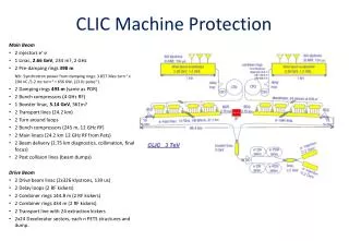
Beam 2 5 LHC 6 4 Beam 1 7 3 TI8 SPS 2 8 TI2 Booster 1 protons LINACS CPS Top energy/GeVCircumference/m Linac2 0.05 30 PSB 1.4 157 CPS 26 628 = 4 PSB SPS 450 6’911 = 11 x PS LHC 7000 26’657 = 27/7 x SPS Ions LEIR PSB = Booster CERN CAS - J. Wenninger
Beam 2 5 LHC 6 4 Beam 1 7 3 TI8 SPS 2 8 TI2 Booster 1 protons Nominal LHC beam LINACS CPS Ions LEIR CERN CAS - J. Wenninger
Livingstone plot of stored energy • Increase at LHC wrt existing accelerators : • A factor 2 in magnetic field • A factor 7 in beam energy • A factor 200 in stored beam energy
Stored energy scales at the LHC b = bunch 450 GeV 156 b physics 450-900 kJ ‘Safe’ Beam Limit - 1012 p 72 kJ Pilot b 360 J Nominal b 8.3 kJ Nominal beam 23.3 MJ Stored Energy (J) 5 TeV ‘Safe’ Beam Limit - 1.7x10¹⁰ p 13.6 kJ 100 1k 10k 100k 1M 10M 100M 1T 156 b physics 5-10 MJ Pilot b 4 kJ Nominal b 92 kJ Nominal beam 258 MJ Stored Energy (J) 100 1k 10k 100k 1M 10M 100M 1T
Beam Dump CERN CAS - J. Wenninger
Beam dumping systems • Beam dumping systems are required to get rid of the beam in case of emergency or when a fresh beam is injected … • Such systems involve: • An absorber (dump) block to contain the beam and the showers created from the beam impact. • >> Can reach high temperature !! • Fast kickers and/or septa magnets to deflect the beam onto the dump block without loosing particles in the rest of the machine. • >> the beam must have a particle free gap for the kicker field rise. • >> high reliability ! • >> must track the energy of the beam. • At CERN only the SPS and the LHC have a dump system. CERN CAS - J. Wenninger
Layout of the LHC beam dump system in IR6 When it is time to get rid of the beams (also in case of emergency!) , the beams are ‘kicked’ out of the ring by a system of kicker magnets and send into a dump block ! 15 septum magnets deflect the beam vertically Beam 1 Q5L 10 kicker magnets dilute the beam Beam dump block Q4L 15 fast ‘kicker’ magnets deflect the beam to the outside 900 m Q4R 500 m Q5R quadrupoles Beam 2
The LHC dump block • This is the ONLY element in the LHC that can withstand the impact of the full beam ! • The block is made of graphite (low Z material) to spread out the hadronic showers over a large volume. • It is actually necessary to paint the beam over the surface to keep the peak energy densities at a tolerable level ! beam absorber (graphite) Approx. 8 m concrete shielding CERN CAS - J. Wenninger
The LHC dump block during the construction phase CERN visit McEwen 29
Passive protection CERN CAS - J. Wenninger
Collimation system • A multi-stage halo cleaning (collimation) system has been designed to protect the LHC magnets from beam induced quenches. • Halo particles are first scattered by the primary collimator (closest to the beam). The scattered particles (forming the secondary halo) are absorbed by the secondary collimators, or scattered to form the tertiary halo. • More than 100 collimators jaws are needed for the nominal LHC beam. • Primary and secondary collimators are made of Carbon to survive severe beam impacts ! • the collimators have a key role for protection as they define the aperture : in (almost) all failure cases the beam will touch collimators first !! Experiment Protection devices Primary collimator Secondary collimators Tertiary collimators Triplet magnets Absorbers Tertiary halo hadronic showers Primary halo particle Secondary halo + hadronic showers Beam CERN CAS - J. Wenninger
Beam impact on collimators G. Robert-Demolaize LHC Note 981 Simulations are needed to define the materials. Temperature increase of a LHC collimator jaw due to beam impact at 7 TeV (from asynchronous dump kicker firing). CERN CAS - J. Wenninger
Collimator settings at 7 TeV • For colliders like HERA, TEVATRON, RHIC, LEP collimators are/were used to reduce backgrounds in the experiments ! But the machines can/could actually operate without collimators ! • At the LHC collimators are essential for machine operation as soon as we have more than a few % of the nominal beam intensity ! The collimator opening corresponds roughly to the size of Spain ! 1 mm Opening ~3-5 mm CERN CAS - J. Wenninger
RF contacts for guiding image currents LHC carbon collimator CERN CAS - J. Wenninger
Failure studies CERN CAS - J. Wenninger
Complex simulations ! • Failure mechanism • Time scale and effect of the failure on the beam must be understood. • Beam particle tracking • The beam particles are tracked in the accelerator, including the time dependent effects of failure. • Potential impact points of the particles with the accelerator aperture are identified. • Particle shower development • The particle showers are tracked through the accelerator equipment using a detailed geometry. • Material state changes • The resulting energy depositions results are used to estimate temperature increases, inelastic deformations etc. CERN CAS - J. Wenninger
Loss map from LHC collimators G. Robert-Demolaize LHC Note 981 Impact distribution of protons scattered from the LHC collimator jaws at 7 TeV and tracked through the LHC lattice: indicates critical regions. CERN CAS - J. Wenninger
Failure simulations • Many failures simulations were performed for the LHC to understand the most critical failures and design adequate protection systems. • They resulted in: • Correct requirements for protection systems. • Design changes and new developments. Typical example : Current decay curves of power converters are used to asses criticality of magnetic circuits. PHD - A. Gomez CERN CAS - J. Wenninger
Timescales for failures@ LHC Time to ‘impact’ Operational ‘mistakes’ 10000 turns = 0.89 s 1000 turns Quenches 100 turns Normal conducting magnet powering failures 10 turns 1 turn = 89 ms Kicker magnets (injection, dump) CERN CAS - J. Wenninger
Simulation result example • The evolution of the beam parameters, here beam orbit, is used to evaluate REACTION times for internal interlocks and for beam diagnostic systems (beam loss monitors). Orbit around collimators Orbit along the ring PHD - A. Gomez Collimator jaw CERN CAS - J. Wenninger
Simulation result example • Assuming a given transverse beam distributions (usually nominal size with Gaussian shape) it is possible to reconstruct the beam lost at various locations versus time to evaluate REACTION times for internal interlocks and for beam diagnostic systems (beam loss monitors). PHD - A. Gomez CERN CAS - J. Wenninger
Failure studies outcome CERN CAS - J. Wenninger
Beam loss monitors • Ionization chambers to detect beam losses: • N2 gas filling at 100 mbar over-pressure, voltage 1.5 kV • Sensitive volume 1.5 l • Requirements (backed by simulations) : • Very fast reaction time ~ ½ turn (40 ms) • Very large dynamic range (> 106) • There are ~3600 chambers distributed over the ring to detect abnormal beam losses and if necessary trigger a beam abort !
FMCMs • Simulations indicated absence of redundancy and very short reaction times for BLMs for failures of some normal-conducting circuits in the LHC. • Led to the development (CERN together with DESY/Hamburg) of so-called FMCMs (Fast Magnet Current change Monitor) that provide protection against fast magnet current changes after powering failures. • Very fast detection (< 1 ms) of voltage changes on the circuit. Tolerances of ~ 10-4 on DI/I achievable. VME Crate CPU + CTRP (or TG8) VIPC626 RS422 link Fast Magnet Current change Monitor Power Converter BIS interface Voltage Divider & Isolation Amplifier resistive magnet
FMCM Test Example Zoom around step time Transfer line dipole PC: >> Steep step programmed into the PC reference to simulate failure • FMCM interlock trigger time: • DI < 0.1 A • DI/I < 0.01% CERN CAS - J. Wenninger
Timescales@ LHC Time 10000 turns = 0.89 s Operational ‘mistakes’ 1000 turns 100 turns Quench protection Quenches Power converter interlocks 10 turns NC magnet powering failures FMCM 1 turn = 89 ms Kicker magnets BPMs BLMs Absorbers LHCb - J. Wenninger
Summary • Machine protection • requires the understanding of the different failure types that could lead to uncontrolled beam loss, • requires comprehensive understanding of all aspects of the accelerator (accelerator physics, operation, equipment, instrumentation), • affects many aspects of accelerator construction and operation, • is becoming increasingly important for future projects, with increased beam power / energy density and increasingly complex machines. CERN CAS - J. Wenninger