Download
1 / 29
290 likes | 448 Vues
Machine Protection and Operations. CLIC workshop WG5 2009 10 15 09:00-10:30. MPO working group. Machine Protection and Operations WG Machine Protection Identify problems Propose solutions Machine Operations Strategy for bringing machine in operation Availability studies

E N D
Machine Protectionand Operations. CLIC workshop WG5 2009 10 15 09:00-10:30
MPO working group Machine Protection and Operations WG • Machine Protection • Identify problems • Propose solutions • Machine Operations • Strategy for bringing machine in operation • Availability studies • Machine commissioning • Safety • Radiation
MPO working group Started in May 2009, hence for CDR • Machine Protection • Identify conceptual problems • Propose a baseline concept for Machine protection • Machine Operations • Strategy for bringing machine in operation • Radiation studies • Availability studies ? Members: B.Holzer, M.Jonker, D.Manglungi, G.Morpurgo, T.Otto, F.Tecker, J.Uythoven
Presentation • General Concept of Machine Protection 9:05 -9:25 M.Jonker • Beam Loss Monitor specifications 9:25 -9:50 B.Holzer - Presented by M.Sapinski • Implications for Power Converters 9:50 -10:10 S.Pittet - Presented by Y.Thurel • First look at beam scenarios 10:10 - 10:30 G.Morpurgo
General Concept of Machine Protection M.Jonker CLIC WS 2009 10 15 for the MPO WG
Machine Protection Objectives: • Protect machine from detrimental effects of ill controlled beam. RISK = impact of failure x frequency of failure • i.e. expectation value of damage due to failures • Can be expressed in a percentage of operational time and a percentage of operational budget Examples of risk expressed in loss of operational availability (6 month scheduled time / year, a failure producing • 3 month down time, once in 5 years => risk equivalent of 7.5 % • 1 day down time, 10 times a year => risk equivalent of 5.5 % • 2 year down time, once in 10000 years => risk equivalent of 0.02 % Machine protection should reduce the risk, either by reducing • impact of failure (passive protections) • frequency of failure (detection and beam abort) to an acceptable level • a fractional percent level (individual risks) • a few percent level (sum of all risks) SIL (Safety Integrity Level) = 10log(risk reduction factor)
CLIC Machine Protection An extensive topic: • Many (8) different accelerator component types (linacs, combiner rings, transport lines, decelerator, damping rings, main linac, beam delivery and diagnostics system, post collision lines). • Many different beams with different characteristics (energy, intensity, brilliance) • Impressive beam power and energy density
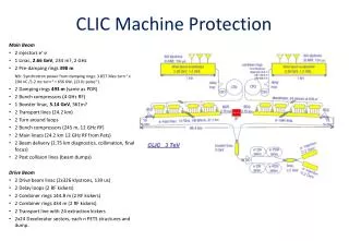
CLIC Machine Protection Main Beam • 2 injectors e+ e- • 1 Linac, 2.2 GeV, 234 m, 2 GHz • 2 Pre-damping rings 365 M NB: Synchrotron power from damping rings: 3.857 Mev turn-1 x 204 nC /1.2 ms turn-1 = 656 KW, (13 KJ pulse-1). • 2 Damping rings 365 M (same as PDR) • 2 Bunch compressors (4 GHz RF) • 1 Booster linac, 6.6 GeV, 561m • 2 Transport lines (24.2 km) • 2 Turn around loops • 2 Bunch compressors (245 m, 12 GHz RF) • 2 Main linacs (24.2 km 12 GHz RF from Pets) • 2 Beam delivery (2.75 km diagnostics, collimation, final focus) • 2 Post collision lines (beam dumps) Drive Beam • 2 Drive beam linac (2x326 klystrons, 139 us) • 2 Delay loops (2 RF kickers) • 2 Combiner rings 144.8 m (2 RF kickers) • 2 Combiner rings 434 m (2 RF kickers) • 2 Transport line with 24 extraction kickers • 2x24 Decelerator sectors, each n PETS structures and dump.
CLIC beams Drive Beam • Uncombined beam 1 out of 24 pulses with reduced pulse length • … • Full combined beam Main Beam • Reduced intensity, reduced number of bunches, enlarged emittance • … • Nominal beam Minimum requirements are (co)defined by Machine Protection requirements For further details see presentation of Giulio Morpurgo
Beams and beam power • CLIC drive beam (2.4 GeV) bunch trainpulse (24 trains)second (50 pulses) Bunches 1 2922 7 0128 3 506 400 Charge [nC ] 8.4 24 544 58 9075 29 453 760 • Time [ns] 0.003 / 0.083 244 140 300 1 s Current [A] 100 100 4.20 0.029 Beam Energy [kJ] 0.020 59 1 413 70 689 • CLIC main beam bunch pulse second (50 pulses) Bunches 1 312 15600 Charge [nC ] 0.60 186 9285 • Time [ns] 0.00015 / 0.5 156 1 s Current [A] 1.2 1.2 9.3 10-6 Beam Energy @2.8 GeV [kJ] 0.0014 0.45 22.3 Beam Energy @9 GeV [kJ] 0.0053 1.69 83.6 Beam Energy @1.5 TeV [kJ] 0.89 278 13927 • LEP (100 GeV) bunch beam total Bunches 1 8 16 Current [mA] 600 5000 10000 Charge [nC ] 53.4 445 890 Beam Energy [KJ] 5.4 45 90
Effect of beam in matter • Note:in energy density in cupper for Melting : 400 J g-1, Structural yield 62 J g-1 Material C Al Cu W • LEP Beam (100GeV, 445 nC) • Energy Density @ shower core [J g-1] 0.64 1.68 22 112 • Energy Density @ IB 0.1 mm2 [J g-1] 778 719 624 510 • CLIC Main Pulse (1.5 TeV, 186 nC, @ collimators) • Energy Density @ shower core [J g-1] 3 9 122 614 • Energy Density @ IB 40 mm2[J g-1] 8.3 105 7.7 1056.7 1055.4 1052.2 103 /bunch • CLIC Main Pulse (2.8 GeV, 204 nC @ DR septum) • Energy Density @ shower core [J g-1] 0.01 0.03 0.34 1.6 • Energy Density @ IB 125 mm2 [J g-1] 2.3 105 2.2 1051.8 1051.5 105600 /bunch CLIC Drive Train (2.4 GeV, 24545 nC) Energy Density @ shower core [J g-1] 1.34 3.08 40 187 • Energy Density @ IB 1 mm2 [J g-1] 4293 3964 34442810
Beam induced damage • Damage to machine structures primarily due to the large charge density. • Microscopic beam size for main beam (104 x safe beam) • High current for drive beam(100 x safe beam) Note: these are orders of magnitude based on melting copper. • However, total beam power makes sustained disposal of the main beam more challenging. (14 MWatt)(drive beam = 300 kW)
Type of failures • Failures causing slow onset of losses • Magnet system • Vacuum system • Slow drifts (alignment, temperature, …) • Failures causing fast losses (“in-flight” failures) • RF breakdown • Kicker misfiring • Klystron trips
Baseline CLIC Machine Protection • Next Pulse permit (slow failures) • if a successful pulse have been delivered previously • and ifno slow equipment failure (power converter, vacuum, positioning) was detected up to 2 ms before next pulse. • elserestart with safe beam • Static Protection (fast losses in lines) • Masks, Spoilers • RT protection (fast losses in rings, drive beam linac) • Kickers, Dumps, Source inhibit, …
Slow losses Avoid slow losses by choosing magnet current circuits with a large time constant: • A power converter is committed to stay within an acceptable tolerance for 2 ms after failure. (See talk of Serge Pittet) • We have time to abort the next pulse in case of failures of a magnet power converter. If so, magnet failures should not be a major issue • But we still have to evaluate the required reliability (SIL) for the interlock system (for the TDR). Likewise: • Positioning systems (free fall in 2 ms = 20 um) • Fast sector valves : if closure speed > ~1 mm / ms, impose a 2 ms closure-inhibit time window.
Protection against fast losses- Oops, we are losing the main beam, can we still dump it? CLIC is essentially a continuous beam line. Fast loss detection and fast dump may catch the tail of the pulse. For the head of the pulse, we must rely on passive protection. Can the passive protection also be robust enough such that we do not need a fast dump?Many studies for collimation system already along these lines (Energy collimation ok) Note: Many processes that causes a loss of the main beam will most likely also spoil its brilliance. Note: There are geographical shortcuts providing opportunities for RT protection (rings, turn around loops)
Beam permits Beam permits Local MP Supervisor Local MP Supervisor Interlocks Interlocks Interlocks Interlocks Interlocks Interlocks Local abort Local abort Local abort Local abort Local abort Local abort Beam permits Beam permits Beam permits Beam permits Beam permits Beam permits Beam permits Beam permits Local MP Supervisor Local MP Supervisor Beam permits Beam permits Beam permits Beam permits Local MP Supervisor Local MP Supervisor Beam permits Beam permits Beam permits Beam permits Master MP Supervisor Network for diagnostics and control hw architecture of MP logic • A central MP supervisor controls 4 parallel Beam-Permit-Chains (BPC) for the two drive and two main beams. • Each Beam permit chain carries the beam permits for different beam types (pilot, tests, nominal). • A Beam-Permit-Chain contains n local nodes with user permit inputs that can inhibit the beam permit chain (in both directions). • In case the beam permit chain is interrupted, the local node will also provide signals that can be used by local beam and equipment abort systems. • Decision time: up to 2 ms before next pulse.After this time machine must be safe by construction
Next pulse permit: 18 ms; post pulse analysis; confirms OK 2 ms: Machine save by construction Time The next pulse is only allowed in the presence of the next pulse permit.This pulse permit is delivered if: a successful pulse have been delivered previouslyConfirmed by post pulse analysis of previous pulse: i.e. beam loss, current, position, profile… within toleranceNote: the post pulse analysis should detect the onset of slow instabilities(See presentation of Barbara Holzer) no slow equipment failure (power converter, magnet positioning, vacuum, RF trips) was detected up to 2 ms before next pulse. (See presentation of Serge Pittet) In case of absence of the next pulse permit: successive test beams of lower intensity, and emittance will have to be used to re-establish the readiness of the machine. (i.e. the permit system is also aware of the beam type) => Establishment of operational procedures (See presentation of Giulio Morpurgo)
Failure Scenario Catalogue of failures, build from • Component classes (e.g., linac, damping ring, …, decelerator … etc • Failure classes (e.g. RF cavity breakdown, spurious kicker firing, power converter trip … Already identified 24 components, 16 fault classes: A few hundred of failure scenario Include Correlated Failures (Multiple RF failures, Mains trips,…) For every entry we need: • Estimated element failure frequency & element multiplicity • Direct effects (availability and financial impacts) Simulation studies • Collateral effects (availability and financial impacts) • Mean time to repair/recover • Procedure to recover next pulse permit • Mean time to re-establish nominal operational condition RISK = Frequency x Impact Risk reduction to bring risk at the percent level of machine operational availability and budget.
Failure scenario(a none exhaustive list…) • Failure Classes • RF System • Cavity Break down • SynchroSystem/Timing error • Powering System HV trip • Kicker Systems • Spurious kick • Timing synchronization error • HV generator Error • RF Deflectors • Cavity Break down • Synchro System Timing error • Powering System HV trip • Magnet Powering System • Power Interlock /Fault • Magnet System • Winding Short • Alignment System • Stabilization System • Control out of range • Beam Feedback system • Control out of Range • Beam Instrumentation System • Beam Dump • Dump Not ready • Collimators, spoilers… • Vacuum System • Bad Vacuum • Fast Vacuum Fault • Environment and infrastructure Components Classes • Main Beam Production • Injectors • PreDamping Rings • Damping Rings • Booster Linac • Transfer to tunnel • Long transfer • Turnaround • Bunch Compressor • Spin Rotator • Drive Beam Production • Linac • Delay Loop • Combiner Ring 1 • Combiner Ring 2 • Transfer to Tunnel • Long Transfer • Turnaround • Bunch Compressor • Two Beam Accelerator /Drive Beam • Turnaround loop • Decelerator • Beam Disposal • Two Beam Accelerator /Main Beam • Accelerator • Interaction Region • Diagnostics Section • Collimation Section • Experiment • Post Collision Line
Conceptual Issues Unlikely to examine all failure scenarios in detail for the CDR. Many failures scenario do not represent a conceptual problem.A different approach For large time scales (> 20 ms ) • post pulse analysis of full beam observation system to detect onset of slow instabilities (ground movements, feedback saturation, etc. etc.) • Need to concern about reliability and certification of post pulse analysis system (hardware / software) • Not a conceptual issue • A conceptual problem would arise if we are not able to detect minute losses and to identify performance problems that will “consume” machine components on time scales of several years. See presentation of Barbara Holzer
Conceptual Issues Short time scales <20 ms or “in flight” failures.A more pragmatic approach: • In every part of the machine • Identify the most restrictive structures • Estimate beam excursions that may affect these structures • Identify equipment failure or other processes that may cause such beam excursions and also • Identify equipment most likely to fail • Identify possible damage caused by these failures
Conceptual IssuesMain Linac (1/3) Example exercise: • Most restrictive structure: Collimators (200 μm opening of spoilers). • Potential damage: Destruction of spoilers • Collimators are consumable: 1 hit – you're out! • Spare surface (8mm), fully consumed after 1 – 10?? impacts (depending on the severity). • Derive maximum kicks, displacements, transverse RF in the Main Linac corresponding to 100 μm. • Note: to kick any of the other sensitive structures (accelerator structures, vacuum chamber) the required kicks are 2 orders of magnitude larger!
Conceptual IssuesMain Linac. (2/3) • Derive maximum kicks, displacements, transverse RF • Sets the scale of failure tolerance to 0.2 μrad (i.e. 20 % of full range) • Idem if using quad positioning for correction (20 % of full range) • Limits the step size in pulse to pulse correction of beam feedback to 20% of max. Is it possible to remain in failure tolerance during 2 ms?See talk of Serge Pettit • RF: problem in case of a break down we have a 1% transverse accelerating kick due to the breakdown current. • Note: Transverse kick from bookshelf effect is much lower (5 keV) • No indications for asymmetries have been observed in the reflected power during breakdowns in acceleration structures (W.Wuensch) • Asymmetric breakdown currents can also have a defocusing effect (which help) • Multiple breakdowns: at 1/100 pulses, 5 fourfold breakdowns/year Looking forward to the results of TBTS and other breakdown studies.
Conceptual IssuesMain Linac. (3/3) Equipment “in flight” failures (a non exhaustive list of examples) • RF breakdown • Multiple RF breakdown • Decelerator train 180O phase error • Decelerator train abort • Multiple decelerator train abort (DriveBeam linac trip) Effects (depending on severity) • Energy error • Beam blow up • Loss of Luminosity • Beam Loss on energy collimator • Beam Loss in linac Many studies on this already performed, no show stoppers
Conceptual Issues Damping rings • Extraction kickers, protection of septum and beam lines • Timing errors, rise time should be sufficiently fast not to pile up bunches on the same spot. To be avoided!! A single bunch is about sufficient to melt copper. • Misfiring of kicker (e.g. one out of two strip lines) may send full beam into septum. Drive beam decelerator • Turn around kickers, protection beam lines and decelerator Drive beam linac • Need to add beam abort kickers and dumps ? Combiner Rings • Need to add beam abort kickers and dumps ? Need to be studied in more detail (kicker reliability could be an issue)
R&D RD effort related to Machine Protection issues The two beam test stand: study the effect of RF break down on the two different beams of CLIC and to confirm simulation studies. Simulation of failure modes, Simulation of beam loss due to failure modes. Simulations for optimal placement of beam loss monitors for diagnostics of the accelerators; or as active components in protection chains. Study /test material damage in material (masks) by dense electron beams (include indirect effects: synchrotron radiation, wakefield heating). Study of activation of accelerator component caused by beam loss. A) implications for control electronics, b) implications for personnel safety (i.e. access restrictions due to hot spots).
Crazy ideas • Dilution kicker to protect collimation spoilers • 10 m upstream, 100 ns rise time • fired by detection of backscatter from spoiler • fired by local beam position error gain factor 3 of main beam train intensity • Other ways of stopping the beam? • septa • permanent non-linear elements • New materials & composites • Ultra fast material cooling, (heat plates) • Laser spoilers, gas jet spoilers • Self healing material (as in space station) • … ?
Conclusion The base line machine protection provides an adequate framework for protection against fast and slow failures. The large amount of time available between pulses allows an exhaustive post pulse analysis to authorize the next pulse. The challenging issues: mask and spoilers to • Intercept a single main bunch up to a full main train • intercept a “derailed” decelerator train. More info is needed to estimate consequences of RF failures. Kickers reliability to be looked into. Your help, feedback & suggestions are very welcome.