Download
1 / 40
610 likes | 1.7k Vues
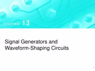
Chapter 12 Signal generators and waveform-shaping circuits . Introduction 12.1 Basic principles of sinusoidal oscillators 12.2 RC oscillator circuits 12.3 LC and crystal oscillators 12.4 Bistable Multivibrators 12.5 Generation of a standardized pulse-The monostable multivibrator.

E N D
Chapter 12 Signal generators and waveform-shaping circuits Introduction 12.1 Basic principles of sinusoidal oscillators 12.2 RC oscillator circuits 12.3 LC and crystal oscillators 12.4 Bistable Multivibrators 12.5 Generation of a standardized pulse-The monostable multivibrator
Introduction • linear oscillators: • employs a positive-feedback loop consisting of an amplifier and an RC or LC frequency-selective network.(Section 13.1-3) • (2)nonlinear oscillators or function generators: • The bistable multivibrator(Section 13.4) • the astable multivibrator(Section 13.5) • the monostablemultivibrator(Section 13.6) The twodifferent approaches
The basic structure of sinusoidaloscillators Amplifier circuit:realize the energy control Frequency-selective network:oscillator frequency is determined Positive feedback loop: amplitude control:implementation of the nonlinear amplitude-stabilization mechanism The basic structure
The oscillator feedback loop The basic structure of a sinusoidal oscillator. A positive-feedback loop is formed by an amplifier and a frequency-selective network. Basic Principles of Sinusoidal Oscillator
Feedback signal xf is summed with a positive sign The gain-with-feedback is The oscillation criterion: Barkhausen criterion. Basic Principles of Sinusoidal Oscillator
Nonlinear amplitude control To ensure that oscillations will start, the Aβ is slightly greater than unity. As the power supply is turned on, oscillation will grown in amplitude. When the amplitude reaches the desired level, the nonlinear network comes into action and cause the Aβ to exactly unity. Basic Principles of Sinusoidal Oscillator
The first approach makes use of a limiter circuit The other mechanism for amplitude control utilizes an element whose resistance can be controlled by the amplitude of the output sinusoid. The implementation of the nonlinear amplitude-stabilization mechanism
A Popular Limiter Circuit for Amplitude Control When vi is close to zero:
A Popular Limiter Circuit for Amplitude Control When vi goes positive,D1 is on, D2 is off
A Popular Limiter Circuit for Amplitude Control • Transfer characteristic of the limiter circuit; • When Rf is removed, the limiter turns into a comparator with the characteristic shown.
Op Amp-RC Oscillator Circuits The Wien-Bridge Oscillator The phase-Shift Oscillator LC-Tuned Oscillator Colpitts oscillator Hareley oscillator Crystal Oscillator Oscillator Circuits
The Wien-Bridge Oscillator A Wien-bridge oscillator without amplitude stabilization.
Analysis of frequency-selectivenetwork for Wien-bridge oscillator (b) Low frequency: 1/wc>>R (c) high frequency: 1/wc<<R
The loop gain transfer function Oscillating frequency To obtain sustained oscillation The Wien-Bridge Oscillator
The Wien-Bridge Oscillator A Wien-bridge oscillator with a limiter used for amplitude control.
The circuit consists of a negative-gain amplifier and three-section RC ladder network. Oscillating frequency is the one that the phase shift of the RC network is 1800 The Phase-Shift Oscillator
The Phase-Shift Oscillator A practical phase-shift oscillator with a limiter for amplitude stabilization.
The LC-Tuned oscillator • Colpitts Oscillator • A parallel LC resonator connected between collector and base. • Feedback is achieved by way of a capacitive divider • Oscillating frequency is determined by the resonance frequency.
The LC-Tuned oscillator • Hartley Oscillator • A parallel LC resonator connected between collector and base. • Feedback is achieved by way of an inductive divider. • Oscillating frequency is determined by the resonance frequency.
Crystal Oscillators A piezoelectric crystal. (a) Circuit symbol. (b) Equivalent circuit.
Crystal Oscillators • Crystal reactance versus frequency (neglecting the small resistance r, ). • A series resonance at • A parallel resonance at
June 12th, 2008 12.13;12.14 Homework:
The output signal only has two states: positive saturation(L+) and negative saturation(L-). The circuit can remain in either state indefinitely and move to the other state only when appropriate triggered.(threshold voltage) The direction of one stage moving to the other stage. A positive feedback loop capable of bistable operation. Bistable Circuit --three basic factors
Bistable Circuit • The bistable circuit (positive feedback loop) • The negative input terminal of the op amp connected to an input signal vI.
Bistable Circuit • The transfer characteristic of the circuit in (a) for increasing vI. • Positive saturation L+ and negative saturation L-
Bistable Circuit The transfer characteristic for decreasing vI.
Bistable Circuit The complete transfer characteristics.
A Bistable Circuit with Noninverting Transfer Characteristics
A Bistable Circuit with Noninverting Transfer Characteristics The transfer characteristic is noninverting.
Comparator is an analog-circuit building block used in a variety applications. To detect the level of an input signal relative to a preset threshold value. To design A/D converter. Include single threshold value and two threshold values. Hysteresis comparator can reject the interference. Application of Bistable Circuit as a Comparator
Application of Bistable Circuit as a Comparator • Block diagram representation and transfer characteristic for a comparator having a reference, or threshold, voltage VR. • Comparator characteristic with hysteresis.
Application of Bistable Circuit as a Comparator Illustrating the use of hysteresis in the comparator characteristics as a means of rejecting interference.
Making the Output Level More Precise For this circuit L+ = VZ1 + VD and L– = –(VZ2 + VD), where VD is the forward diode drop.
Making the Output Level More Precise For this circuit L+ = VZ + VD1 + VD2 and L– = –(VZ + VD3 + VD4).
Generation of Square Waveforms Connecting a bistable multivibrator with inverting transfer characteristics in a feedback loop with an RC circuit results in a square-wave generator.
Generation of Square Waveforms The circuit obtained when the bistable multivibrator is implemented with the positive feedback loop circuit.
Waveforms at various nodes of the circuit in (b). This circuit is called an astable multivibrator. Time period T = T1+T2
June 19th,2008 12.28; 12.32; 12.33 Homework: