Download
1 / 21
210 likes | 298 Vues
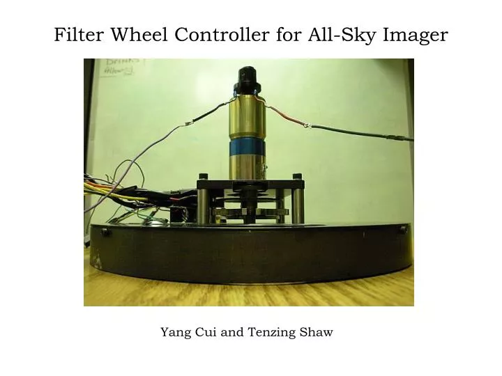
Filter Wheel Controller for All-Sky Imager. Yang Cui and Tenzing Shaw. Block Diagram. PIC-PC Communication. RS-232 serial communication using PIC UART and DB9 serial cable connector MAX232 chip to convert voltage levels. PIC-PC Communication. Instruction Set:

E N D
Filter Wheel Controller for All-Sky Imager Yang Cui and Tenzing Shaw
PIC-PC Communication • RS-232 serial communication using PIC UART and DB9 serial cable connector • MAX232 chip to convert voltage levels
PIC-PC Communication Instruction Set: • Change_Filter(Filter #, Direction) • Change_DS(New_DS) • Heater_On • Heater_Off • Set_Reference(Reference_Voltage) • Read_Temperature
Motor Control Brake Direction PWM
Infrared Diode Encoding System HOA6961-T51 Gap Detector Detector Output = 1 Output = 0 HOA696X/697X Datasheet http://parts.digikey.com/1/parts/946683-sensor-digital-slot-optoschmitt-hoa6961-t51.html
0 1 1 1 0 0 0 1 0 To PIC 0 0 1 1 0 1 Encoding System
2 5 3 1 4 1 3 4 3 2 5 4 3 2 2 1 4 1 5 5 Position Control Algorithm Idle Receive Change_Filter (001) Brake = 0 Start Motor Brake = 1 Continue Moving No Sensor Reading = Target Filter? Yes Still True? No Yes Delay 0.2 s
System should be stand-alone One 5V (0.25A), one 12V (1.2A) Acopian power supplies chosen for high-reliability Possible problem with 5V supply, which further testing could not reproduce Power Supplies http://www.acopian.com/single-l-pcb-p.html
Heating device • A heater (~16W) was already installed on the filter wheel • Planned to use a scheme similar to proportional control • Used a thermistor to measure temperature • Used PIC’s build in voltage comparator as heating trigger • The heater is physically controlled by a relay
Thermistor • A thermistor is a special kind of resistor whose resistance varies with changes in temperature. • NTC = negative temperature coefficient • PTC = positive temperature coefficient
Linearization • Ro = resistance value at room temperature To = (25°C 298.15K) • Behavior can be linearlized using voltage divider technique
RED: RL=2KΩ GREEN: RL=1K Ω
PIC Voltage Comparator • The PIC16F877A has a build-in voltage comparator that has 2 modes of operation: internal and external voltage reference. http://ww1.microchip.com/downloads/en/DeviceDoc/30292c.pdf
Relays • The heater uses 110V AC power. Since we needed to control it with a ~5V DC circuit, a relay was necessary. • We cascaded two relays. This was due to safety considerations: the two levels of relay help to further separate the control circuit from the high-voltage circuit.
Graphical user interface Current active filter User defined reference temperature List of named filters Button to turn the wheel We also planned to add an automatic mode, but have not implement it yet.
Steps Remaining for Completion • Complete temperature control scheme • Complete graphical user interface • Interface camera with GUI via MaxIm DL software • Scale-up 5V power supply by one size to 0.5 A