Download
1 / 29
320 likes | 623 Vues
A Low-Jitter 8-to-10GHz Distributed DLL for Multiple-Phase Clock Generation. Keng-Jan Hsiao and Tai-Cheng Lee National Taiwan University Taipei, Taiwan. Outline. Motivation System Architecture System Model Circuit Details Experimental Results Conclusion. Introductions.

E N D
A Low-Jitter 8-to-10GHz Distributed DLL for Multiple-Phase Clock Generation Keng-Jan Hsiao and Tai-Cheng Lee National Taiwan University Taipei, Taiwan
Outline • Motivation • System Architecture • System Model • Circuit Details • Experimental Results • Conclusion
Introductions • Multiple-Phase Clock Generators • Time-Interleaved System • I/O Interface Circuits • DLL-Based Frequency Multiplier • Issues • Phase Accuracy • Jitter Performance
Conventional DLL • Only one output phase is monitored. H.-H. Chang et al, IEEE J. of Solid-State Circuits, May, 2006.
DLL with Phase Calibration Circuit • Delay cell tuning. • Output buffer tuning. Federico Barontiet all,IEEE J. of Solid-State Circuits, Feb., 2004. H.-H. Chang et al, IEEE J. of Solid-State Circuits, May, 2006.
Jitter Accumulation • Jitter accumulates along the delay line. • More delay cells = Larger jitter.
Distributed DLL(DDLL) • All output phases are monitored. • Reduce phase mismatch and jitter.
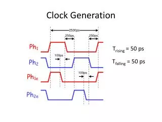
Locking Process of the DDLL • Conceptual demonstration of the DDLL.
System Architecture • Each delay cell is independently tuned.
Closed-loop Characteristics • Lumped model:
Phase Relationship of Multiple-Phases • Different clock tracks different Ref. edge.
System Model Open-loop Gain: System Function:
Settling Behavior • The simulation result matches the proposed model.
Stability Constraint • The open-loop gain must reduce as the number of delay cells increases.
Sources of Jitter • Vn,cell : Noise from delay cells. • Vn,con : Noise from the control voltage.
NTF of the Noise of Delay Cells • Noise at the last output clock, Vp4.
NTF of the Common Noise • Noise at all output phases , Vp1~Vp4.
Pseudo-differential Delay Cell • Pseudo-differential architecture. • Differentially controlled. • Output buffer isolates output loading.
Phase Detecter • Time Domain Voltage Domain
Voltage-to-Current Convertor • Continuous-time common-mode feedback. • Loop capacitors are realized on-chip.
Die Photo Active Area = 0.03 mm2
8.5GHz Output Waveform RMS Jitter : 643.5fs RMS Jitter : 417.6fs P-P Jitter : 5.67ps P-P Jitter : 4.22ps Contributed Jitter : 578.9fs Contributed Jitter : 308.1fs RMS Jitter of Ref. Clk : 281.0fs Conventional DLL Distributed DLL
10GHz Output Waveform RMS Jitter : 443.8fs RMS Jitter : 293.3fs P-P Jitter : 3.18ps P-P Jitter : 2.04ps Contributed Jitter : 366.7fs Contributed Jitter : 153.4fs RMS Jitter of Ref. Clk : 256.8fs Conventional DLL Distributed DLL
Conclusion • The distributed DLL achieves low jitter and high phase accuracy. • Linear model of the proposed distributed DLL is provided.