Download
1 / 10
120 likes | 479 Vues
Numerical Control I. NC - Numerical Control - Software control of manufacturing processes. Based on a code of letters, numbers & special characters called a program.

E N D
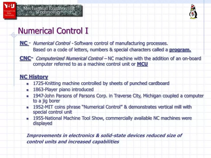
Numerical Control I NC - Numerical Control - Software control of manufacturing processes. Based on a code of letters, numbers & special characters called a program. CNC- Computerized Numerical Control – NC machine with the addition of an on-board computer referred to as a machine control unit or MCU NC History • 1725-Knitting machine controlled by sheets of punched cardboard • 1863-Player piano introduced • 1947-John Parsons of Parsons Corp. in Traverse City, Michigan coupled a computer to a jig borer • 1952-MIT coins phrase “Numerical Control” & demonstrates vertical mill with special control unit • 1955-National Machine Tool Show, commercially available NC machines were displayed Improvements in electronics & solid-state devices reduced size of control units and increased capabilities
Numerical Control I Applications of NC Chip producing machines: Drills, Mills, Lathes, Bores, Saws, Etc. Chipless machining: Flame Cutting, Punches, Wire EDM, Welding, Non machining: Paint Spraying, Tube Bending, Assembly, Etc. NC used to 1) Position cutter (move table) 2) Change tooling 3) Adjust coolant flow (flood/mist-on/off) 4) Adjust spindle speeds 5) Perform operations at a point (plunge, tap, bore, etc.)
Numerical Control I STEPS INVOLVED ON GENERAL PURPOSE MACHINE: OperationOff MachineOn Machine Plan operation sequence X Select tools X Set and change tools X Select feeds and speeds X Set feeds and speeds X* Position work X Start and stop machine operations X* Control path between work & tool X during cutting Rapid position tool for next cut or X part unloading * Performed via Numerical Control software
Numerical Control I Circumstances best suited to NC • Mass production quantities • Complex geometries • Tight tolerances • Replacement parts • Parts subject to modification
Numerical Control I Advantages of Numerical Control • Greater operator efficiency • Greater operator safety • Reduction of scrap • Reduced lead time for production • Fewer chances for human error • Maximal accuracy and interchangeability of parts • Lower tooling costs • Increased productivity • Minimal spare parts inventory • Greater machine tool safety • Fewer man hours for inspection • Greater machine utilization
Numerical Control I Role of the Operator • Execute Machine Control Unit(MCU) or Console Setups • Start and Stop Machines • Load and Unload Workpieces • Maintain High- Level Machine Tool Performance Standards • Change NC Inputs as Necessary (Per Engineering) • “Feedback” Information to Programmer/Engineer
Numerical Control I Programming methods for NC • MANUAL (#4) • COMPUTER ASSISTED • Language (#5A) • Graphic (#5B)
Numerical Control I Two ways information is fed into an NC machine. • Auxiliary Operations: Tool change, spindle reversal, tool on/off, coolant on/off, spindle speeds (RPM), spindle feeds (IPM) • Geometrical Machine Movements: • Translation – X , Y , Z • Rotation – about X , Y , Z axis
Numerical Control I Any movement under control of NC input is called an axis. (ie) • 2 axis machine: X,Y control (usually lathe) • 3 axis machine: X,Y,Z control • 4 axis machine: X,Y,Z, one rotational control • 5 axis machine: X,Y,Z, two rotational control *often called machining centers and include tool changes… Toshiba – 9 axis mill for sub propellers
Numerical Control I To specify coordinate points to a machine tool, there are two positioning point reference systems. (#7) • Absolute: all measurements are taken from a fixed origin (X=0,Y=0,Z=0) *helpful to have part prints with baseline dimensioning* • Incremental: all measurements for the next position are made from the last or previous position