Download
1 / 28
290 likes | 299 Vues
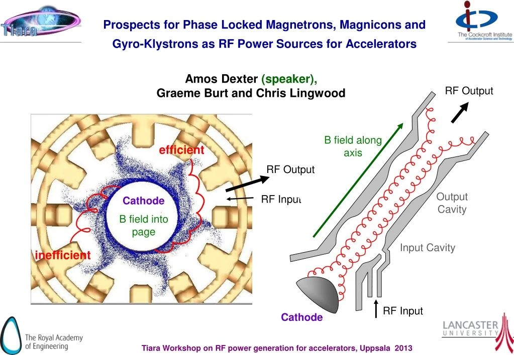
Prospects for Phase Locked Magnetrons, Magnicons and Gyro-Klystrons as RF Power Sources for Accelerators. RF Output. B field along axis. Output Cavity. Input Cavity. RF Input. Amos Dexter (speaker), Graeme Burt and Chris Lingwood. efficient. RF Output. RF Input. Cathode.

E N D
Prospects for Phase Locked Magnetrons, Magnicons and Gyro-Klystrons as RF Power Sources for Accelerators RF Output B field along axis Output Cavity Input Cavity RF Input Amos Dexter (speaker), Graeme Burt and Chris Lingwood efficient RF Output RF Input Cathode B field into page inefficient Cathode
Bunching Magnetrons, Magnicons and Gyro-Klystrons all have electron orbits that circulate around the magnetic fields lines. Bunching is in the orbit around the magnetic field. The Gyro-Klystron uses a magnetron injection gun (MIG) so the transverse momentum is created close to the gun. Bunching is partly ballastic but also depends on the relativistic cyclotron maser instability. The Magniconstarts with a linear beam and then employs synchronous rotating modes in deflection cavities to spin and bunch the beam. Output for the Gyro-klystronand the Magniconis a bremsstrahlung process in a “fast wave” output cavity. In a Magnetronelectrons have no motion in the direction of the magnetic field. Bunching occurs by the interaction of circulating electrons and the slow wave structure of the anode. As electrons are collected on the capacitive gaps of the slow wave structure hence output can be viewed simply as the synchronous charging of a circuit. As electrons are retarded by the slow wave output it is also a Cherenkov process.
Groups with recent work on/relevant to cross field devices for accelerators Phase locked magnetrons Varian Associates (MA) (1991) Treado, Hansen, Jenkins (Short pulse) Univ. Mitchigan (-2013) Gilgenbach et al. (Relativistic Magnetrons) Univ. Lancaster (2003 – 2010) Dexter, Tahir, Carter, Burt (CW Cooker type) J-Lab (2006 – 2013) Wang (CW Cooker type) Muon Inc. , Fermi-Lab & (2007 – 2013) Kazakevich, Yakovlev (Power combining) Efficient L Band Magnetrons SLAC, CTL, Raytheon Tantawi et al. (2004) (CW Coaxial? 300kW) Diado Instit. Tech. Japan (1991) Shibata (1991) (CW Coaxial 600kW Gyro Klystrons IAP Nizhny Novgorad Lebedev Univ. Maryland Lawson Calabazas Creek Magnicons Budker Inst. Nonosibirsk Kozyrev, Makarov, Omega-P Inc, & Yale Nezhevenko, LaPointe, Shchelkunov, Yakovlev, Hirshfield Gyro TWT(Univ. Strathclyde, MIT ,IAP Nizhny Novgorad, Univ. Maryland , NRL Washington, Univ. Mitchigan)
Magnetrons for Accelerators Single magnetrons 2.856 GHz, 5 MW, 3ms pulse, 200 Hz repetition are used to power linacs for medical and security applications. Multiple magnetrons have been considered for high energy normal conducting linacs but the injection power needed for an unstabilised magnetron made it uncompetitive with a Klystron. Overett, T.; Bowles, E.; Remsen, D. B.; Smith, R. E., III; Thomas, G. E. “ Phase Locked Magnetrons as Accelerator RF Sources” PAC 1987 Benford J., Sze H., Woo W., Smith R., and Harteneck B., “Phase locking of relativistic magnetrons” Phys. Rev.Lett., vol. 62, no. 4, pp. 969, 1989. Treado T. A., Hansen T. A., and Jenkins D.J. “Power-combining and injection locking magnetrons for accelerator applications,” Proc IEEE Particle Accelerator Conf., San Francisco, CA 1991. Chen, S. C.; Bekefi, G.; Temkin, R. J. “ Injection Locking of a Long-Pulse Relativistic Magnetron” PAC 1991 Treado, T. A.; Brown, P. D.; Hansen, T. A.; Aiguier, D. J. “ Phase locking of two long-pulse, high-power magnetrons” , IEEE Trans. Plasma Science, vol 22, p616-625, 1994 Treado, Todd A.; Brown, Paul D., Aiguier, Darrell “New experimental results at long pulse and high repetition rate, from Varian's phase-locked magnetron array program” Proceedings Intense Microwave Pulses, SPIE vol. 1872, July 1993 Courtesy of e2v
Gyro-Klystron Experimental results For a review of klystrons verses other source for the NLC see http://www.slac.stanford.edu/econf/C10630/papers/T301.pdf
CPI study: Gyroklystron 30 GHz, 50 MW made a design study for CERN in 2001. A 200 MW power station would consist of • four 50 MW Gyroklystrons, 1.2 μs, 100 Hz with fundamental TE011 coaxial cavities, • four SC 2 T solenoids + power supplies, (≈ 300 k$ each) • two 15 kW drivers + power supplies, (≈ 370 k$ each) • one modulator 500 kV, 1.2 kA, (≈ 1000 k$ ) • two power combiners 50 MW + 50 MW (≈ 20 k$ each) • ancillary systems. Lead time ≈3 years (15 months for first 50 MW amplifier) This example would sum up to 7.5 M$
Opportunities for Magnetrons Lancaster started worked on phase locked magnetrons in 2003 The conceptual application was for intense proton beams as would be required for a neutrino factory or future neutron spallation sources. Magnetrons can become an option for intense proton beams where they give significantly greater efficiency than other devices and bring down the lifetime cost of the machine without sacrificing performance and reliability. The easiest applications are where beam quality is not a key issue. One would consider using multiple magnetrons to drive an accelerator unless cost and efficiency are potentially show stopping considerations.
Magnetron Size at 704 MHz air cooling for cathode water cooling for anode dg dm Magnets The magnetron easily fits in the accelerator tunnel and this might offer huge unexpected savings. hm If an accelerator magnetron design is similar to industrial heating magnetron design, has similar tolerances and can be made on same production line then cost may not be much more air cooling input for dome
The Reflection Amplifier Cavity Load Magnetron Circulator Injection Source • Linacs require accurate phase control • Phase control requires an amplifier • Magnetrons can be operated as reflection amplifiers • They run in saturation which is a problem Compared to Klystrons, in general Magnetrons - are smaller -can be more efficient at L band - can use permanent magnets (at 704 MHz) - utilise lower d.c. voltage but higher current - are easier to manufacture Consequently they are expected to be much cheaper to purchase and operate J. Kline “The magnetron as a negative-resistance amplifier,” IRE Transactions on Electron Devices, vol. ED-8, Nov 1961 H.L. Thal and R.G. Lock, “Locking of magnetrons by an injected r.f. signal”, IEEE Trans. MTT, vol. 13, 1965
Reflection Amplifier Controllability 0o towards magnetron Arcing Moding 900 W 800 W 700 W VSWR 6 2 3 4 90o 270o +5MHz +2.5MHz -5MHz +0MHz -2.5MHz 180o • Phase of output follows the phase of the input signal (amplifier in saturation) • Phase shift through magnetron depends on difference between input frequency and the magnetrons natural frequency (same as driving a cavity with a source) • Output power has minimal dependence on input signal power • Phase shift through magnetron depends on input signal power • There is a time constant associated with the output phase following the input phase • Magnetron frequency and output vary together as a consequence of • Varying the magnetic field • Varying the anode current (pushing) • Varying the reflected power (pulling) 915MHz 916MHz Anode Voltage 10kW 20kW 30kW 40kW 3.00A 12.0 kV 11.5 kV 2.92A Power supply load line 2.85A 11.0 kV 2.78A 10.5 kV 2.70A Magnetic field coil current 10.0 kV 1 2 3 4 5 Anode Current Amps
Adler’s Equation for Injection Locking J.C. Slater “The Phasing of Magnetrons” MIT Technical Report 35, 1947 Shien Chi Chen “Growth and frequency Pushing effects in Relativistic Magnetron Phase – Locking”, IEEE Trans. on Plasma Science Vol. 18 No 3. June 1990. The basic circuit model for the phased locked magnetron is the same as for a cavity Injection Load impedance includes pulling effects. Negative impedance to represent magnetron spokes excitation of the anode. Includes static pushing effects. -ZS C Zw L R To get Adler’s equation set to give
Solution of Adler’s Equation Like for small y hence phase stabilises to a constant offset womagnetron ang. oscillation frequency without injection winjinjection angular frequency yphase shift between injection input and magnetron output Vinj /RFequivalent circuit voltage for injection signal / RF output Adler’s equation predicts that :- if wo = withen y→ 0 if wo close to withen y→ a fixed value (i.e. when sin y < 1 then locking occurs) if wofar fromwithen y→ no locking unless Vinj is large Steady state If the natural frequency of the magnetron is fluctuating then the phase y will be fluctuating. High frequency phase jitter will be filtered by a superconducting the cavity Advancing or retarding the injection signal allows low frequency jitter to be cancelled and the magnetron phase or the cavity phase to be maintained with respect to a reference signal.
Power Needed for Injection Locking The minimum locking power is given when sin y = 1 PRF is output power QL refers to the loaded magnetron. Pushing For our 2.45 GHz cooker magnetron (fi –fo) due to ripple ~ 2 MHz (fi –fo) due to temperature fluctuation > 5 MHz This is big hence must reduce fi – fo ( can do this dynamically using the pushing curve) ~ 400 ns ~ 1000 RF cycles Time response ~
Experiments at Lancaster Double Balance Mixer Oscilloscope 2 Stub Tuner 2 Loop Coupler 3 Stub Tuner 1 Water Load Loop Coupler Circulator 1 10 Vane Magnetron Water Load 1W Amplifier Circulator 2 C3 Load Power supply ripple IQ Modulator (Amplitude & phase shifter) D/A Oscilloscope A/D D/A Magnetron phase no LLRF DSP LP Filter 8 kHz cut-off Digital Phase Detector 1.3GHz D/A ÷ M ÷ M pk-pk 26o High Voltage Transformer Magnetron phase with LLRF pk-pk 1.2o Micro-Controller 40kHz Chopper Frequency Divider / N 2.3 - 2.6 GHz PLL Oscillator ADF4113 + VCO 10 MHz TCXO 1ppm Pulse Width Modulator SG 2525 Divider / R 1.5 kW Power Supply Phase - Freq Detector & Charge Pump Loop Filter 325 V DC + 5% 100 Hz ripple ADF 4113
Experiments at Lancaster 0 dBm RBW = 100Hz Span = 100 kHz Centre = 2.44998488 GHz -50 dBm -100 dBm +50 kHz -50 kHz Tahir I., Dexter A.C and Carter R.G. “Noise Performance of Frequency and Phase Locked CW Magnetrons operated as current controlled oscillators”, IEEE Trans. Elec. Dev,vol 52, no 9, 2005, pp2096-2130 Tahir I., Dexter A.C and Carter R.G., “Frequency and Phase Modulation Performance on an Injection-Locked CW Magnetron”, IEEE Trans. Elec. Dev,vol. 53, no 7, 2006, pp1721-1729 Phase shift keying the magnetron Lancaster has successfully demonstrated the injection locking of a cooker magnetron with as little as -40 dB injection power by fine control the anode current to compensate shifts in the natural frequency of the magnetron. Locked spectral output
Proof of principle Demonstration of CW 2.45 GHz magnetron driving a specially manufactured superconducting cavity in a VTF at JLab and the control of phase in the presence of microphonics was successful.
SCRF cavity powered with magnetron Injection + magnetron on +control Injection but magnetron off Injection + magnetron on
Magnetron study for CERN’s SPL? • Would like to phase each cavity individually • Cavity power requirements increase to ~ 900 kW • Klystrons more cost effective at the 3-10 MW scale • IOTs not available to get to 900 kW • Long pulse L magnetrons should be able to reach 1 MW • Hence use IOTs along the linac up to that point power is insufficient • After that point use IOTs to injection lock magnetrons • Obtain high efficiency where most power is required • Obtain best control at front of linac
Layout using one magnetron per cavity Permits fast phase control but only slow, full range amplitude control Cavity Standard Modulator 880 kW Magnetron Load 4 Port Circulator Pulse to pulse amplitude can be varied Slow tuner LLRF ~ -13 dB to -17 dB needed for locking i.e. between 18 kW and 44kW hence between 42 kW and 16 kW available for fast amplitude control 60 kW IOT Could fill cavity with IOT then pulse magnetron when beam arrives
How do we get high efficiency? Using standard theory one can estimate Magnetic field, anode and cathode radii from requirement data (frequency 704 MHz, efficiency >90% and power Should be able to use same block for efficient generation at both the 500 KW and 1 MW level
Expected operating range Threshold for moding Short circuit regime VORPAL simulations
PIC code simulations Voltage in magnetron The literature suggests that PIC codes give the correct predictions for inefficient magnetrons with solid cathodes. Our simulations have never accurately reproduced performance curves of efficient cook magnetrons with spiral cathodes. Volts time (s) Volts time (s) FFT (dB) time (s)
Efficient Orbits An efficient orbit should have no loop Orbits associated with the design on the previous slides
Prospects • Intense beams in future user facilities need to be generated efficiently . • Developing a new HPRF source is expensive and comparison to available sources is difficult before development is mature. • One would not use a magnetron for a superconducting linac if you could afford a klystron or IOT. • One would not fund the development a new gyro-klystron with the same specification as a klystron which already exists. • Universities will continue to explore new concepts. • Need accelerator labs to explore new devices at accelerator test stands to have any chance of new devices becoming feasible alternatives. • Future accelerators constrained on cost so research on efficient low cost sources is worthwhile.