Download
1 / 29
290 likes | 529 Vues
The APS Vacuum System An Allegory for Accelerator Vacuum System Design John Noonan APS Engineering Support Division Argonne National Laboratory Beam Instrumentation Workshop 2006 May 5, 2006. Allegory: expression using symbolic fictional generalizations about human experience

E N D
The APS Vacuum SystemAn Allegory for Accelerator Vacuum System DesignJohn NoonanAPS Engineering Support DivisionArgonne National LaboratoryBeam Instrumentation Workshop 2006May 5, 2006 Allegory: expression using symbolic fictional generalizations about human experience x symbolic representation
Talk Outline • The APS • Vacuum System Design Criteria • APS Accelerator Vacuum Systems, Chambers, Absorbers • Materials, Cleaning, Pumping, Flanging, Magnetic Permeability • Advantages, Problems • Modern Materials and Processes • Summary: 100 % Complete
APS parameters • The APS is a third generation, hard x-ray, synchrotron light source • The storage ring operates at 7 GeV, 100 mA • The nominal stored electrons/ bunch is 2.3 x 10¹² • The natural emittance is 2.5 nm-rad • There are 70 beamline ports, for which there are ~ 40 beamlines operating during a run. • The APS consistently operates at >98.5 % availability, and currently is above 99%.
The design criteria for accelerator vacuum systems is very simple: Q = SP where Q is the gas load, S is the pumping speed, and P is system pressure. Q = Q thermal outgassing + Q stimulated desorption 1/S = 1/Spump + 1/C , where C is the pipe conductance and P is the design criteria
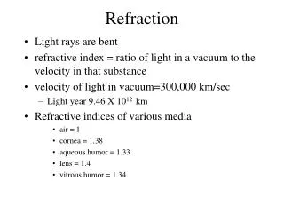
Gas Loads • Thermal Outgassing: • Typical outgassing rates are in the literature, such as NASA publication 1124, rev. 2, Outgassing Data for Selecting Spacecraft Materials, W. A. Campbell, Jr. and John J. Scialdene, c 1990. • For example, after 24 hrs, unbaked Al has Q ~ 1 x 10⁻¹⁰ torr-l/s/cm2 • baked Al Q ~ 5 x 10-13 • Stimulated desorption • N = 1.82 X 10²¹ photons/sec at 7 GeV, 300 mA • So Q = N* (ηγ)*K, ηγ = 2 x 10⁻⁷ mol/photon, K = 3.11 x 10⁻²⁰ torr-l/mol
LINAC • The LINAC has two vacuum systems, the accelerating structures, and the transmission waveguide. • Both systems are unbaked, ion pump systems using ConFlat flanges in the accelerating linac, but Varian flanges in waveguide. • The problem is high RF power producing arcing and multipactoring
LINAC design • The LINAC water load has a vacuum-to-water joint • To isolate the water load from accelerating structures, we have installed ceramic RF windows to isolate one section from another. However now pumps are needed on both sides of the window • As a result there are more pumps than required for a design pressure of 10-7, so the linac operates at < 5 x 10⁻⁹ torr. • The second major criteria is elimination of arcing and multi-pactoring. The obvious solution is smooth surfaces and rounded, not sharp corners.
Storage Ring design • The design criteria for the storage ring vacuum system was 20 hour residual gas lifetime, which led to 1 x 10⁻⁹ torr. • The original criteria was to absorb x-rays on the walls of the vacuum chambers, therefore, distributed pumping was included in the design. • As will be discussed later, photon absorbers are needed to shield vacuum components, such as ends of chambers. To capture the gas desorbed by the photons, pumps were installed below the absorbers. • The pumps at the absorbers are closer together than the 1 ntorr criteria. As a result, the storage ring base pressure is 3 x 10-11 , and the operating pressure at 100 mA beam is 2 x 10⁻¹⁰ torr.
Aluminum vacuum chamber design • Machined Al extrusion has beam chamber and antechamber for neg pump • Welded plates and equipment ports • Neg carrier inserted into slot • Water channels are also part of extrusion
Details of storage ring vacuum chamber • RF BPM ports machined into the chamber • One fixed support in ~ middle, two supports at end • Turbo pump installed in each sector for rapid recovery of venting • Fluorescence from absorbers is greater than expected • Tolerance gap between chamber and magnet is 3 mm
Insertion device vacuum chamber • The insertion device vacuum uses the same technology as the sector chambers, but there are significant differences • The standard interior vertical dimension is 8 mm, with 1 mm walls. There is one 5 mm gap chamber in the storage ring. • The large holes are to maintain material flow balance in the extrusion dye.
Absorbers: ray tracing The x-ray fan from bending magnets are calculated for a storage ring sector. A single absorber does not stop the radiation fan because it would extend to far into the beam chamber, creating a large aperture change, and large beam impedance. 95% of the power is absorbed in the storage ring vacuum system. Only 5% is transported to the experimental beam lines. Nevertheless, they are still among the most intense bending magnet beamlines operating today.
Bending magnet x-ray absorbers • The APS bending magnets generate enormous photon power density, • One of the engineering achievements at APS was the design of a simple structure that could withstand ~13 kW of power.* • The device could be installed through a 10” port, and had several novel design features, including glid-cop brazing, EDM water channels, and had a temperature rise to ~270 C. • *I.C. Sheng, S. Sharma, E. Rotela and J. Howell, PAC 1995
Materials • Aluminum Easily extruded Thickest chamber wall • Low Cost Large eddy current • Efficient heat removal High secondary e yield • Low resistivity Yield strength fails at < 1700 C Cu Can be extruded Material cost increasing Efficient heat removal Eddy current Low resistivity Yield strength maintained through 2500 C anneal Stainless Steel Thinnest wall chamber High cost High strength Poor heat removal Low eddy current High resistance Anneal to > 4500 C
Chambers • The APS used extruded 6063 T6 alloy Al, this Al strengthened by Si and Mg for the storage ring vacuum chambers • The end plates and flanges were 2219 alloy Al, which is strengthened by Cu. This is the most compatible alloy for welding to 6063. • ( In a development with LBNL, Argonne developed a technology to weld 6063 to 6063 using high Mg doped Al weld rod.)
Flanging • The chambers were flanged using ConFlat technology, but with Al flanges. • The Al ConFlat flanges were bolted to stainless steel flanges, such as bellows, spool pieces, pumps, etc. • The original joint failure rate was 1 %, but this lead to 2 leaks for every 3 bakes. Using the procedure, the failure rate is < 10-4 leaks per bake. • A special bake-out procedure was developed to maintain vacuum integrity between the Al and stainless steel: • The bake temperature was ramped at <10 degrees per hour. • The temperature across the joint was kept < 12 degrees • The temperature in the flange plane was uniform to <2 degrees.
Pumping All of the accelerator vacuum systems use all metal seals and are ion pumped. So the system is isolated from atmosphere There was a plan to have turbo-molecular pumps on the RF cavities operating all of the time. There are turbo’s on the RF cavities, but they are operated only for high gas load times. The storage ring has additional non-evaporable getter pumps A distributed neg strip Concentrated 250 l/s and 1000 l/s pumps at the absorbers The gas loads are sufficiently low, that the neg pumps are only used after sectors are vented to atmospheric pressure (dry nitrogen purge). This helps to reduce the thermal outgassing load.
Cleaning vacuum surfaces for UHV compatibility • Cleaning accelerator vacuum chambers required acids and caustics until recently. SLAC and CERN have prescriptions for cleaning copper, stainless, aluminum, etc for vacuum pipes. Solvents were used to clean parts. The cost of large tanks of alcohols, acetone, and especially, trichloroethylene was prohibited and difficult to manage with modern pollution restrictions. • Modern detergents were used to clean small parts for vacuum service. The APS (I believe) is the first to clean the whole system for UHV service • The detergents have been approved for environmental compatibility. • Detergent cleaning is not a panacea. Different materials require different detergents, e.g. Ritoline (Almeco) for Al and Citranox for Cu and SS. • Heavy organics and silicone contamination are not removed with the standard detergents. The way to deal with organics is to review the complete manufacturing process so that the detergents can clean the cutting fluids, etc.
The detergent cleaning was developed, and monitored using XPS. Citranox cleaning of Cu and Ritoline (Almeco) cleaning of Al are compared with other detergents. Heated water and ultrasonic transducers are essential for detergent cleaning. New materials must be tested to find the best detergent, bath temperature and ultrasonic power. Coatings are special problems, since the two materials Might not be mutually compatible. Carbon-to-Copper XPS ratio
Magnetic Permeability from “Magnetic Properties of Undulator Vacuum Chamber Materials for the Linac Coherent Light Source” by SH Lee presented at FEL2005 Permeability measurement results of 20Cb-3 (Alloy 20) at ANL Central Shops by SH Lee on 4/7/04 Plate: 1.010~1.012 – 19 mm thk (most points 1.010) Sheet: 1.004~1.006 – 1.5 mm thk (most points 1.005), after correcting for thickness the values are 1.008~1.012 with an average of 1.010.
Advantages • The vacuum system uptime is ~99.9%. The mean time between failures is > 8,000 hours. • Bremstrahlung radiation is well below predictions. The radiation transported to beamlines is shielded to mrem levels. • The low operating pressures allows for special operating modes. Top up injection times are 2 minutes, which allows enough time for Most experimental scans to be completed. Low emittance beam operation is achieveable. In principle, these should mitigate residual gas lifetimes; however, for low lifetimes, the electron gun must generate more charge per bunch.
Problems • Water Corrosion • Copper cooling lines blocked • Al-SS fittings corroded • Al-to-SS flange leak after bake • Neg strip carrier shorted out • Carrier connection failed reducing the distance between stand-offs • New carrier cannot override another and there is an insulating strip to prevent shorting. • Chamber microwave resonance interferes with BPM measurement
New technologies for the next “APS” • Manufacturing has advanced significantly since the APS was built. • The pictures show two advantages of a new technology, ultrasonic bonding to fabricate a solid. • Metal foil is ultrasonically bonded to produce near-bulk density solids • Water channels can be integrated into the part • Sensors, such as thermocouples and optical fiber can be integrated into the part • Strengthening layers can be built in also
New Technologies • Computer controlled machining centers allow designers to think beyond mills and lathes. Using solid model CAD, complex shapes can now be fabricated. • Y.C. Chae is developing a database of impedance calculations for different apertures. By contouring aperture changes, chamber impedances can be reduced significantly. • Curved chambers can also be designed using computer controlled machines. Fabrication costs can be reduced. For example, forming curved chambers for the booster cost over $ 150K. Using a new tube forming machine, the quotation was $30K (that includes the die)
Summary • The APS accelerator vacuum systems met or exceeded the original design specifications • The x-ray beam absorbers can withstand 13 kW of power—in fact they can withstand significantly more power before reaching the fatique failure • Environmentally safe cleaning techniques were developed and have been shown to be UHV compatible, even for large systems • Baking the storage ring greatly improves the base pressure, and is essential to special machine operating modes • It was not until I had to deal with the APS vacuum systems that I learned what “100% complete” really meant.