Download
1 / 19
190 likes | 300 Vues
Datao Gong On behalf of the ATLAS Liquid Argon Calorimeter Group Department of Physics, Southern Methodist University Dallas Texas 75275, U.S.A. dtgong@physics.smu.edu. Introduction. Design of LOCs1. Lab and Irradiation Test. Plan - LOCs6. Summary. Outline. Introduction.

E N D
Datao Gong On behalf of the ATLAS Liquid Argon Calorimeter Group Department of Physics, Southern Methodist University Dallas Texas 75275, U.S.A. dtgong@physics.smu.edu
Introduction Design of LOCs1 Lab and Irradiation Test Plan - LOCs6 Summary • Outline
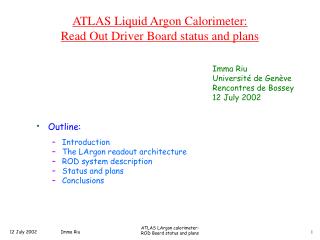
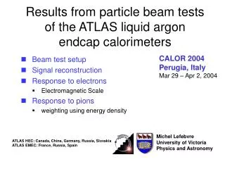
Introduction architecture of the proposed FEB for upgrade The ATLAS detector There are 128 channels on each Front End Board (FEB). A total of 1524 FEBs are read out by optical links. For the upgrade, it is proposed to remove L1 trigger from the front end. Data from ADC will be streamed off the detector. The requirements for the link upgrade: • 100 Gbps data rate per FEB. • 20% redundancy to improve the link reliability. • Power: 80 W/FEB leads to a proposal of 20 W/link, 100 mW/Gbps for the serializer • Radiation tolerance.
Why Silicon on Sapphire (SOS) ? SOS is one type of Silicon on Insulator (SOI) CMOS technology. Transistors are manufactured on a thin silicon layer grown on top of a sapphire wafer. The substrate is the insulating sapphire crystal instead of silicon. • Eliminates the parasitic drain capacitance Fast • Reduces the crosstalk between circuit elements Low noise • Makes transistor radiation tolerant • - Total Ionizing Dose (TID) effects are negligible when substrate is • grounded. • - Better Single-event effects (SEE) immunity than bulk CMOS. • There is no Single-event Latchup (SEL) mechanism. • Radiation tolerance at transistor level greatly simplifies our design task. More details about the radiation tolerance of SOS CMOS technology can be seen in Michael King’s poster (Poster ID# 27).
Design of LOCs1 3 mm 3 mm Die micrograph Design diagram More design details can be found in the poster session of TWEPP 2009. Ring oscillator based PLL provides clocks up to 2.5 GHz 16:1 CMOS multiplexer has a tree architecture 5 Gbps serial data output through a differential CML driver Submitted for fabrication in Aug 2009 and delivered in Nov 2009
Test Setup in Lab • 12 Chips wire bonded • 7 boards work 463 ±13 mW @ 5Gbps • 5 boards do not work: 2 boards power open 2 boards power short 1 board has a stuck bit Chip or wire bonding problem?—more tests with demo-link will tell. LOCS1 #1 FPGA board provides 312.5 MHz clock and 16 bit parallel data to a chip carrier board, both in LVDS 5 Gbps PRBS serial data output to an oscilloscope or BERT for measurements.
Eye diagram at 5 Gbps and eye mask adapted from FC 4.25 Gbps and scaled up to 5 Gbps • Lab test with an oscilloscope Eye diagram at 5 Gbps The mask is adapted from FC 4.25 Gbps and scaled up to 5 Gbps The measurements are made with Tektronix DSA 72004 and differential probe P7380SMA.
Lab test with a BERT 5.8 Gbps 5 Gbps The measurements are made with Anritsu MP1763C and MP1764C as clock generator and error detector. • Eye opening at BER of 10-12 is 122±18 ps at 5 Gbps • Data rate range at BER of 10-12 varies board by board Lower limit from 3.8 to 4.0 Gbps Upper limit from 5.7 to 6.2 Gbps
The FPGA board provides parallel data and clock to LOCs1. Altera Stratix II GX signal integrity evaluation board functions as the deserializer and error detector. Sinusoidal jitter is injected on the reference clock of LOCs1. Complete error information is recorded in a log file in PC. Jitter tolerance is larger than 1.8 UI when jitter frequency less than 1.56 MHz • Lab test with the VBERT VBERT is a powerful and portable BER test system developed at SMU for both in lab and irradiation tests Please see Annie Xiang’s poster (poster ID# 89) for details.
Test setup: 200 MeV Proton beam at IUCF Two LOCs1 chips (#6 and #12 ) inside the beam are running throughout the test One LOCs1 chip (#9) works in shielded area as reference SEE are checked by VBERT which is also shielded Test results: SEE: Cross section is small. See next slide TID: 1. Chips are functionally running during the beam test; 2. No bit error is observed after beam test; 3. Total power supply currents change less than 6% during the irradiation. • Proton beam test at IUCF Beam Stop
SEE analysis • Two types SEE errors observed: • Single bit errors • A total of 5 bits flipped during the test. The links continue to function. • Synchronization errors • A burst of few bits flipped in a duration up to 80 bits as shown in this plot. This burst of errors follows a shift (for- or backward) of one bit in the received data. • Cause still under investigation. Possible reason: SEU in transmitter clock unit induced word misalignment in the receiver. • The link can be recovered at receiver side by making word alignment.
Two serializer chips with a 12-way fiber ribbon per FEB. Each chip has an array of six 16:1 serializers each running at 10 Gbps. One of the six serializers can be configured as a redundant channel. The clock unit may be shared by the serializers to reduce the power. • Next version — LOCs6 Parallel optical link may be a solution for 100 Gbps data rate/FEB
10 Gbps 16:1 serializer design diagram The key components needed to be redesigned: 1. 5 GHz LCPLL, LC VCO 2. CML driver for 10 Gbps 3. 2:1 MUX @ 5GHz • 5 GHz Divider • Clock buffer • The core part of this serializer has same architecture as LOCs1. • A few components need to be redesigned for 5 GHz operation frequency. • We choose to use CML circuit for its low noise and high speed performance.
Tuning range: 4.7 to 5 GHz. Expected: 3.79 to 5.01 GHz. Found a bug in the divider in PLL. Power consumption: 121 mW Compare: Ring oscillator based PLL, 173 mW at 2.5 GHz Random jitter: 1 - 2.5 ps (RMS) Deterministic jitter:< 17 ps (pk-pk) • 5 GHz LC PLL We have tested the first version of LC PLL on the same die as LOCs1. More details are available in T.Liu’s poster (Poster ID# 116) output clock locks to input clock The LC PLL will be used in 10 Gbps serializer with two changes: Slightly adjust the frequency. Fix the bug in the divider.
Bandwidth: ~5 GHz Data rate: up to 8.5 Gbps Plan to use inductive peaking to boost its bandwidth for 10 Gbps data transmission • CML driver We have tested a separate CML driver on the die, same design as used in LOCs1: CML driver test schematic output clock locks to input clock
Swing > 200 mV Freq > 5 GHz Power: ~8 mW Two stage design Fan out two identical buffer without signal attenuation • High speed CML circuit design We designed a CML buffer for 5 GHz clock fan-out. More CML circuit components are ongoing. Parameters for the CML buffer: Schematic and Layout of the CML buffer
CML buffer Post-layout simulation V(v) Output Gain Input V(v) 5 GHz time (ns) Frequency (Hz) Input and output of CML buffer at typical corner and room temperature Frequency response at different temp and corners • CML buffer fans out two identical buffer above 5GHz at different corners and temperature based on post-layout simulation 17
Successfully designed LOCs1, a 5 Gbps 16:1 serializer chip. Both laboratory and irradiation tests indicate that we have achieved the design goals. We have started to design LOCs6, a 6 lane serializer array with 10 Gbps/lane to deliver 50 Gbps/chip with 20% redundancy or 60 Gbps/chip without redundancy. The approach looks promising so far. • Summary
Acknowledgments We thank US-ATLAS for funding this project. We are grateful for all the people who have been assisting us in the design and testing of the LOC chips. We are especially in debt to Paulo Moreira, Fukun Tang and Christine Hu for their help in the design of LOCs1. Thank you!