Download
1 / 20
200 likes | 390 Vues
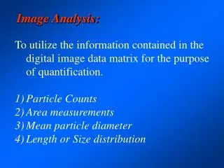
Image Analysis. Preprocessing ROI Image Geometry. Preprocessing. To makes the primary data reduction and analysis task easier.

E N D
Image Analysis Preprocessing ROI Image Geometry
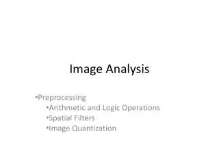
Preprocessing • To makes the primary data reduction and analysis task easier. • They include operations related to extracting regions of interest, performing basic algebraic operations on images, enhancing specific image features and reducing data in both resolution and brightness. • a stage where the requirements are typically obvious and simple, such as the removal of artifacts from images, or the elimination of image information that is not required for the application. • For example, in one application we needed to eliminate borders from the images that had been digitized from film (the film frames); in another we had to mask out rulers that were present in skin tumor slides. • Another example of a preprocessing step involves a robotic gripper that needs to pick and place an object; for this, we reduce a gray-level image to a binary (two-valued) image that contains all the information necessary to discern he object's outline.
Region of Interest Image Geometry • to investigate more closely a specific area within the image - a Region-of-Interest (ROI) • To do this we need operations that modify the spatial coordinate of the image, and these are categorized as image geometry operation • The image geometry operations include crop, zoom, enlarge, shrink, translate, and rotate.
image crop process is the process of selecting a portion of the image, a sub-image, and cutting it away from the rest of the image that's how the border was removed in fig3.2.l(b). • Then zoom in by enlarging it. • Image enlargement is useful in a variety of applications since it can help visual analysis of detailed object.
a) b) c) d) Figure 3.2-1 Preprocessing examples. a) an image needing border removal, b) the image after the border is removed, c) an image where only shape information is necessary in order to control a robotic gripper, d) the image after unnecessary information removal which leaves only the object shape
zoom process can be done in numerous ways, a zero- order hold or a first-order hoId. • A zero-order hold is performed by repeating previous pixeI value ,thus creating a blocky effect (give example). • To extend the image size with a first-order hold we do linear interpolation between adjacent pixels. • A comparison of the images resulting from these two methods is shown in Fig 3.2.2.
Figure 3.2-2 Zooming Methods a) Original image. The ape’s face will be zoomed, b) Image enlarged by zero-order hold, notice the blocky effect, c) Image enlarged by first-order hold. Note the smoother effect b) c) a)
Although the implementation of the zero-order hold is straightforward, the first-order hold is more complicated. • The easiest way to do this is to find the average value between two pixeI and use that as the pixel value between those two; we can do this for the row first (example) • This method will allow to enlarge an N x N sezed image to a (2N -1) x (2N – 1) & can be repeated as desired.
Another method that achieve a similar result requires a mathematical process called convolution. • With this method of image enlargement a two-step process • extend the image by adding row and columns of zero between the existing rows and column, and • perform the convolution. • Example.
The convolution process requires us to overlay the mask on the image, multiply the coincident values, and sum all the results. • This is equivalent to finding the vector inner product of the mask with the underlying sub-image. • For example, if we put the mask over the upper left corner of the image, we obtain (from right to left, and top to bottom): • 0(0) + 1/2(0) + 0(0) + 1/2(0) + 1(3) + 1/2(0) + 0(0) + 1/2(0) + 0(0) = 3
note that the existing image values do not change. • The next step is to slide the mask over by one pixel and repeat the process, as follows: 0(0) + 1/2(0) + 0(0) + 1/2(3) + 1(0) + 1/2(5) + 0(0) + 1/2(0) + 0(0) = 4
note this is the average of the two existing neighbor . • This process continues until we get to the end of the row, each time placing the result of the operation in the Iocation corresponding to the center of the mask. • One the end of the row is reached, the mask is moved down one row and the process is repeated row by row until this procedure has been performed on the entire image; the process of sliding, multiplying, and summing is called convolution (s e Figure 3.2.3).
note that for this mask we will need to put the result in the pixel location corresponding to the lower right corner, since there is no center pixel.
The above methods will only to enlarge an image by a factor of (2N -1), but what if we want to enlarge an image by something other than a factor of (2N - I)? • To do this we need to apply a more general method; we take two adjacent values and linearly interpolate more than one value between them. • This linear interpolation technique is equivalent to finding the line that connects the two values in the brightness space and sampling it faster to get more samples, thus artificially increasing the resolution.
This is done by defining an enlargement number K, then following this process: • subtract the two adjacent values, • divide the result by K, • add that result to the smaller value, and keep adding the result from (2) in a running total until all (K - 1) intermediate pixel locations are filled.
Example 3.2.1 • We want to enlarge an image to three times its original size, and we have two adjacent pixel values 125 and 140. • Find the difference between the two values, 140 - 125=15. • Enlargement desired is K =3, we get 15/3 = 5. • Next determine how many intermediate pixel values we need: K - 1=3 - 1=2. The two pixel values between the 125 and 140 are : 125 + 5 = 130 and 125 + 2 x 5 = 135
Two other operations of interest for the ROI image geometry are translation and rotation. • These process may be performed for many application-specific reason, for example to align an image with a known template in a pattern matching process ,or to make certain image details easier to see. • The translation process can be done with the following equations: • r' = r + ro • c' = c + co where r' and c' are the new coordinate, r and c are the original coordinates and ro and co are the distances to move, or translate ,the image.
The rotation process require the use of these equations: • where and are the new coordinates, r and c are the original coordinates, and θis the angle to rotate the image. • θ is defined in a clockwise direction from the horizontal axis at the image origin in the upper left corner.
The rotation and translation process can be combined into 1 set of equations: