Download
1 / 15
150 likes | 156 Vues
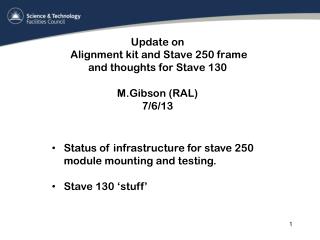
Update on alignment kit and stave 250 frame M.Gibson (RAL). Overall photo of the installation. and one bridge structure. Prototype stavelet frame from QMUL. One bridge structure. light strip for pin hole illumination. Alignment laser.

E N D
Overall photo of the installation. and one bridge structure Prototype stavelet frame from QMUL One bridge structure light strip for pin hole illumination Alignment laser
Two bridge structures sitting adjacent to each other at the correct spacing. one can see the Y and the combined X and theta adjusters Moveable upper bridge to which is fixed the Y stage and vacuum jig Y adjuster Fixed lower bridge Combined X and Theta
Detail of one bridge structure sitting over a prototype stavelet This space required for side mounted SMD version
Under granite store with one storage pod completed. Awaiting more bits from OM Detail of under granite store
Stave frame clamp base fulcrum Lifting screw Fixed base Awaiting the clamp arms
Basic Vacuum Jig Components Pillar to link jig to Y stage from underneath One of three vacuum cups and connectors Floating vacuum connection from lower jig to outside world Edge supports Two of 4 load springs Bottom plate Ball joints Top plate Bottom plate
Free state of jig Fixed plate to provide X,Y and theta At maximum extension ball is entirely within the top plate Lifting plate to give Z Silicon edge to provide compression to on detector Contact to stave surface
Items still being worked on • Awaiting delivery of the required wall components.(OM at RAL) • Awaiting delivery of the required storage components (OM at RAL) • Ivan is working on the software but see ‘current problems’ • The two part self aligning jigs are progressing, hopefully sticking and alignment trials next week
Current Problems • Unfortunately the aluminium section that supports the optics has a CTE that is too big. (It is also in Y the critical direction. The plan is to replace it with a simple fabricated Carbon Fibre (CF) box section using Pultruded CF square tubes and commercially available CF sheet . • Sketch almost ready for construction.
Proposed stave 250 frame basic outline Frame for stave 250 Flexibles to accommodate changes in length as satve and frame are cooled Movable clamp to hold stave cooling pipes Swaglok self sealing quick release couplings
Working drawing soon to be passed out for comment to wire bonders, electrical testers etc. Frame has top and bottom covers and the entire frame sits in an insulated box for testing purposes .
Other box related issues • Material for the outer insulative box is at RAL. Aluminium faced panel with 25mm thick insulation (same as the current box but thicker) .Waiting for final sign off on stave 250 frame to get dims correct. Will have a double glazed window. • Will be fabricated at RAL just like all the other boxes.
Module Shipping • I gather from Peter (P) that we will be receiving modules in at least 2 types of shipping boxes for stave 250. With frame and without frame • I encourage you to make only ONE solution for the real thing. Because.... A) This minimises the chance of operator error (two boxes = double the chance of a mistake) B) we will need only ONE solution to the how to get from box to vacuum jig problem C) It will speed up the process. D) We should try and reduce the handling steps ‘cos they are always fraught! E) At least one of these current solutions means no electrical checking prior to mounting!