Download
1 / 31
320 likes | 337 Vues
Chapter 4 Circuit-Switching Networks. 指導老師 : 陳明仕 教授. 第一組報告 Transport Networks 吳欣典 M9308455 Circuit Switching Networks 盧相平 M9308383 Cellular Telephone Networks 劉昆憲 M9316901. Agenda Multiplexing SONET Transport Networks. (a). (b). A.

E N D
Chapter 4 Circuit-Switching Networks 指導老師: 陳明仕 教授 第一組報告 Transport Networks 吳欣典 M9308455 Circuit Switching Networks 盧相平 M9308383 Cellular Telephone Networks 劉昆憲 M9316901
Agenda Multiplexing SONET Transport Networks
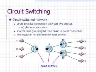
(a) (b) A A A A B B MUX MUX B B C C C C Multiplexing • Multiplexing involves the sharing of a transmission channel (resource) by several connections or information flows • Channel = 1 wire, 1 optical fiber, or 1 frequency band • Significant economies of scale can be achieved by combining many signals into one • Fewer wires/pole; fiber replaces thousands of cables • Implicit or explicit information is required to demultiplex the information flows. Shared Channel
Channel divided into frequency slots Guard bands required AM or FM radio stations TV stations in air or cable Analog telephone systems B f A f 0 Wu C C 0 Wu f 0 Wu B A f W 0 Frequency-Division Multiplexing (a) Individual signals occupy Wu Hz (b) Combined signal fits into channel bandwidth
A1 A2 … t 0T 6T 3T B1 B2 … t 6T 3T 0T C1 C2 … t 0T 6T 3T C2 A2 B2 … A1 C1 B1 t 0T 1T 2T 3T 4T 5T 6T Time-Division Multiplexing (a) Each signal transmits 1 unit every 3T seconds • High-speed digital channel divided into time slots • Framing required • Telephone digital transmission • Digital transmission in backbone network (b) Combined signal transmits 1 unit every T seconds
1 1 2 MUX 2 MUX . . . . . . 22 23 24 b 24 2 1 b . . . Frame 24 24 T-Carrier System • Digital telephone system uses TDM. • PCM voice channel is basic unit for TDM • 1 channel = 8 bits/sample x 8000 samples/sec. = 64 kbps • T-1 carrier carries Digital Signal 1 (DS-1) that combines 24 voice channels into a digital stream: Framing bit • Bit Rate = 8000 frames/sec. x (1 + 8 x 24) bits/frame • = 1.544 Mbps
North American Digital Multiplexing Hierarchy Pointer Processing Multiplexing Aligning Mapping • 1 N C-4 AUG STM-N AU-4 VC-4 139,264 Kbps SDH • 3 X1 美規 PDH (DS3) 44,736 Kbps 歐規 PDH (E3) 34,368 Kbps C-3 AU-3 VC-3 STM-0 SONET • 7 • 1 TUG-2 美規 PDH (DS2) 6,312 Kbps TU-2 VC-2 C-2 • 3 歐規 PDH (E1) 2,048 Kbps TU-12 VC-12 C-12 • 4 美規 PDH (DS1) 1,544 Kbps TU-11 VC-11 C-11
CCITT Digital Hierarchy Pointer Processing Multiplexing Aligning Mapping • 1 N C-4 AUG STM-N AU-4 VC-4 139,264 Kbps • 3 • 1 TUG-3 TU-3 VC-3 • 3 SDH 美規 PDH (DS3) 44,736 Kbps 歐規 PDH (E3) 34,368 Kbps C-3 AU-3 VC-3 SONET • 7 • 7 • 1 TUG-2 美規 PDH (DS2) 6,312 Kbps TU-2 VC-2 C-2 C : Container (信號櫃) VC : Virtual Container (虛擲信號櫃) TU : Tributary Unit (支路單元) TUG : Tributary Unit Group (支路單元群) AU : Administrative Unit (管理單元) AUG : Administrative Unit Group (管理單元群) STM : Synchronous Transport Module (同步傳輸模組) • 3 歐規 PDH (E1) 2,048 Kbps TU-12 VC-12 C-12 • 4 美規 PDH (DS1) 1,544 Kbps TU-11 VC-11 C-11
Optical fiber link carries several wavelengths From few (4-8) to many (64-160) wavelengths per fiber Imagine prism combining different colors into single beam Each wavelength carries a high-speed stream Each wavelength can carry different format signal e.g. 1 Gbps, 2.5 Gbps, or 10 Gbps Optical deMUX Optical MUX 1 1 2 1 2 2. m Optical fiber m m Wavelength-Division Multiplexing
Agenda Multiplexing SONET Transport Networks
SONET: Overview • 同步光纖網路﹙Synchronous Optical NETwork,SONET﹚的概念係由美國貝爾實驗室最早提出。美國國家標準協會ANSI於1988年通過了兩個最早的SONET標準,即關於光介面速率及碼框格式的標準。 • SDH傳送網路有兩種標準: • 一種為美規SDH﹙一般為SONET﹚,應用於北美地區 • 一種為歐規SDH,廣泛應用於北美以外世界各地,國際間通信亦規定必須採用此一標準,可說是一種國際標準 • 8000 frames/sec. (Tframe = 125 sec) • 在數位階層信號中最基本的模組信號是STM-1,其位元速率為155.520 Mbit/s。 • STM-N為將N路STM-1經位元組間插多工後之高速信號,其中N為正整數,且為4的倍數。 • OA&M support to facilitate network management • Protection & restoration
ETSI SONET Bit Rate Mbit/s Signal Designation Signal Designation Level Level OC-1 OC-3 OC-9 OC-12 OC-18 OC-24 OC-36 OC-48 STS-1 STS-3 STS-9 STS-12 STS-18 STS-24 STS-36 STS-48 51.840 155.520 466.560 622.080 933.120 1244.160 1866.240 2488.320 1 4 16 STM-1 STM-4 STM-16 Bit Rates and Level Designations 9953.28 64 STM-64 39813.12 256 STM-256 STS = Synchr.Transport Signal OC = Optical Carrier STM = Synchr.Transport Module Bit Rates in Mbit/s
DS1 Low-speed mapping function DS2 STS-1 E1 51.84 Mbps Medium speed mapping function DS3 STS-1 44.736 OC-n STS-n STS-1 STS-1 High- speed mapping function E4 STS-1 STS-1 Scrambler E/O STS-1 STS-1 139.264 . . . . . . STS-3c MUX STS-3c High- speed mapping function ATM or POS SONET Multiplexing
9 * 270(bytes/frame) * 8(bits/byte) * 8000(bits/sec)] * N = 155.52 * N Mbps
STM-1 Frame Structure 125m s STS-N Serial Signal Stream N * 155.52 Mbps N * 2430 bytes RSOH 270 * N Columns(bytes) Transport Overhead 9 Rows Path Overhead 261 * N Columns(bytes) 9 * N Columns(bytes) MSOH [9 * 270(bytes/frame) * 8(bits/byte) * 8000(bits/sec)] * N = 155.52 * N Mbps 區段管理位元SOH) 再生器區段管理位元組 1. 1. 1. 1. 酬載本體 AU 指標 -----------------------管理單元AU------------------ 多工器區段管理位元組
Agenda Multiplexing SONET Transport Networks
傳輸設備 ONU Lease Line xDSL FITL POTS POTS ISDN 寬頻網路系統架構示意圖 Core Edge Access User 台北 CPE 內湖 CO (ATM+IP+ ITLS+ADM) Router HUB-ADM FITL VP-ring LMDS CABLE ATM-A - FR/IP MUX.. ATM+IP +ADM Hub Ring PBX 本地傳輸Local Ring CO (ATM+IP+ TLS+ADM) LL 匯接局( HUB Node ) ISDN PRA ATM 骨幹傳輸網路 National Backbone Ring HUB-ADM 台中 台中 接取局( Access Node ) FR/IP Building Ring Ethernet ATM+IP +ADM Building Ring B-AMX xDSL POTS ISDN BRA xDSL PBX 三重 B-AMX 大樓電信室 ( Curb / Building ) B-AMX CO (ATM+IP+ ITLS+ADM) 高雄
SONET Rings (ADM Networks) MUX DEMUX ADM Insert tributary Remove tributary
W T R Bridge Selector R T P Protection Schemes :1+1 Linear Automatic Protection Switching T = Transmitter W = Working line R = Receiver P = Protection line • Simultaneous transmission over diverse routes • Monitoring of signal quality • Fast switching in response to signal degradation • 100% redundant bandwidth
Switch Switch W R T APS signaling T R P 1:1 Linear APS • Transmission on working fiber • Signal for switch to protection route in response to signal degradation • Can carry extra (preemptible traffic) on protection line
Switch Switch W 1 T R W ² T R … … … … W … n T R P T R APS signaling 1:N Linear APS • Transmission on diverse routes; protect for 1 fault • Reverts to original working channel after repair • More bandwidth efficient
Two-Fiber Unidirectional Path Switched Ring 1 W 2 4 P W = Working Paths P = Protection Paths • No spatial re-use Each path uses 2x bw 3
UPSR path recovery 1 W 2 4 P W = Working line P = Protection line 3
UPSR Properties • Low complexity • Fast path protection • 2 TX, 2 RX • No spatial re-use; ok for hub traffic pattern • Suitable for lower-speed access networks • Different delay between W and P path
4-BLSR :Four-Fiber Bidirectional Line Switched Ring 1 Equal delay W P Standby bandwidth is shared 2 4 Spatial Reuse 3
BLSR Span Switching 1 W Equal delay P • Span Switching restores failed line 2 4 Fault on working links 3
BLSR Span Switching 1 W Equal delay P • Line Switching restores failed lines 2 4 Fault on working and protection links 3
4-BLSR Properties • High complexity: signalling required • Fast line protection for restricted distance (1200 km) and number of nodes (16) • 4 TX, 4 RX • Spatial re-use; higher bandwidth efficiency • Good for uniform traffic pattern • Suitable for high-speed backbone networks • Multiple simultaneous faults can be handled
Regional ring Metro ring Interoffice rings Backbone Networks consist of Interconnected Rings UPSR OC-12 BLSR OC-48, OC-192 UPSR or BLSR OC-12, OC-48