Download
1 / 33
330 likes | 336 Vues
RUNOFF COMPUTATIONS IN HEC-HMS Unit and Drirrect Flow Hydrograph and Routing. Dr. Duc Hoang Nguyen Assistant Professor Water Engineering and Management (WEM) Asian Institute of Technology (AIT). Training on Hydrological Modelling for Water Accounting

E N D
RUNOFF COMPUTATIONS IN HEC-HMS Unit and Drirrect Flow Hydrograph and Routing Dr. Duc Hoang Nguyen Assistant Professor Water Engineering and Management (WEM) Asian Institute of Technology (AIT) Training on Hydrological Modelling for Water Accounting Asian Institute of Technology, Thailand December 18-24, 2017
Learning Outcomes • Comprehending different methods for transforming the excess rainfall into direct runoff • Understanding unit hydrograph derivation • Understanding the base flow component and separation methods in HEC-HMS • Understanding different methods included in HEC-HMS for the channel routing, and know how to compute the travel time and attenuation of water flowing in open channels
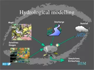
Direct Runoff Transformation Loss Computation (Pervious surface) Flow Computation (Direct flow) Meteorological Component • Runoff computation process Channel Routing Total Sub-basin Runoff Outlet Discharge • Excess precipitation is transformed to the direct flow by using the Unit Hydrograph (UH)
Unit Hydrograph (UH) • UH is a direct runoff hydrograph resulting from one unit (1 inch or 1 cm) of effective (net) rainfall occurred uniformly over the entire watershed at a uniform rate for a specified duration • The role of UH is to provide an estimate of direct runoff hydrograph (DRH) resulting from given excess rainfall hyetograph
Direct Runoff Hydrograph (DRH) • A sample of DRH computation
Direct Runoff Hydrograph (DRH) Time of concentration, tc = hydraulic length/velocity tc is the time required for runoff to travel from the most distant point of the watershed to the outlet
Factors Influencing the DRH • Other factors: • Rainfall intensity and pattern • Rainfall duration • Spatial rainfall distribution
Determination of UH • In a gaged sub-basin where rainfall and stream flow date are available, we can derive the UH directly • In an ungaged sub-basin, a synthetic UH can be derived indirectly using the runoff data (not rainfall) and sub-basin characteristics, including: • Basin size, slope, shape • Storage characteristics • Stream length • Land forms • Channel and land surface roughness • Soil type
Synthetic UH Techniques Available in HEC-HMS • Synthetic UH techniques relate the peak flow and timing to one or two parameters of the basin characteristics by means of empirical and theoretical analyses • HEC-HMS utilizes different synthetic UH techniques as shown below: • Snyder UH • Clark UH (Time-Area) • SCS UH • ModClark UH • User-defined UH • Quasi-distributed linear transform • Conceptual kinematic wave model
Synthetic UH Techniques: Snyder UH • Input Variables • tp : Snyder Lag (hr) • Cp: Snyder Cp • A: Basin Area (km2) • tR: Time interval Output Variable: unitgraph ordinates (m3/s per mm of excess) Standard UH (when tpR=5.5tR) tpR=tp-(tr-tR)/4 (when tpR≠5.5tR) tr tR tpR tp qP=2.75*Cp/tp Discharge per unit area qpR qPR=qP*tp/tpR qp Discharge per unit area W75 W50 tb Time Time
Synthetic UH Techniques: Clark UH • Parameters • Time of Concentration: The time of flow from the farthest point on the watershed to the outlet • Storage Time: Storage constant R with the linear reservoir model: St = R*Ot • Process of the Clark UH • Estimate the contribution area with • Time-area relationship • Calculate the average inflow Itto the storage at time t • Calculate the UH ordinates by
Tr Excess Rainfall Tr/2 tp Direct Runoff qp Tp tb Synthetic UH Techniques: SCS UH qp: Peak runoff (m3/s) C:2.08 for SI A: Basin Area (km2) Tp: Time of rise Tr: Excess Duration (hour) Tp: lag time (hour) Tc: Time of concentration (hour)
Synthetic UH Techniques • Recommendation for the selection of synthetic UH methods The choice of a UH method should be based on: • Availability of information for calibration and parameter estimation • Appropriateness of the model assumptions, and • User preference and experience
Baseflow • The direct runoff hydrograph is the hydrograph resulting from excess precipitation over the watershed after the losses (abstractions) are removed • The baseflow is the background flow that results from prior storm flows, general draining of the basin, etc. direct runoff baseflow
Baseflow Separation • To actually analyze hydrographs or prepare for rainfall-runoff modeling, the storm flow has to be extracted from the observed hydrograph • This analytical process is called base flow separation • In HMS we can specify base flow models and use calibration to separate • Or we can do the separation independently • Two types of separation are common in engineering modeling • Constant (wastewater discharge that flows in a channel) • Declining baseflow from bank storage
Baseflow Separation Constant slope Constant discharge Concave
Sub-basin Baseflow • There have been different methods available in HEC-HMS for the baseflow
Total flow Discharge Recession threshold Time Sub-basin Baseflow: Recession • If the total flow > recession threshold at falling or rising limbs • If the total flow < recession threshold Qb: base flow Q0: initial base flow K: recession constant T: time Qt: total flow Qr: flow where recession starts tr: time when recession starts Baseflow
Q t Flow Routing • What is flow routing • Routing simulates movement of water discharge (flood wave) as it transports downstream • Allows modeling of a basin comprised of interconnected sub-basins • Accounts for storage within the reach and flow resistance
Flow Routing • Why we route flows
Routing Hydrographs • Routing is the process of predicting temporal and spatial variation of a flood wave as it travels through a river (or channel) reach or reservoir
Types of Flow Routing • Lumped/Hydrologiccal • Flow is calculated as a function of time alone at a particular location • Governed by continuity equation and flow/storage relationship • Require less data and provide results quickly • Distributed/Hydraulic • Flow is calculated as a function of space and time throughout the system • Governed by continuity and momentum equations
Flow Routing in HEC-HMS • Routing methods: • Kinematic wave • Lag • Modified Puls • Muskingum • Muskingum-Cunge • Straddle stagger
Hydrological Flow Routing • Basic Equations • The equation of continuity used in all hydrologic routing states that the difference between the inflow and outflow rate is equal to the rate of change of storage I – Q = dS/dt where I = inflow rate; Q = outflow rate; S = storage
Hydrological Flow Routing • Basic Equations • In a small time interval t, the difference between the total inflow and total outflow volumes in a reach is equal to the change in storage in that reach • In a small time interval t, the difference between the inflow and outflow volumes in a reach • The time interval tshould be small so that the inflow and outflow hydrographs can be assumed to have straight line in that time interval
Hydrological Flow Routing • Considering the Inflow and outflow hydrographs at a small river section. Area A volume of water that fills the section and Area C is the volume of water that flows out • At time t < t1: dS/dt > 0 • At t1: the channel is full and inflow = outflow • At time t > t1: inflow has been slowed (storm is past) dS/dt < 0, so water will drop
Hydrological Flow Routing • Channel routing: Muskingum method • Study changes in flood hydrograph as it travels downs a river or channel • Storage is linear function of I and Q Wedge and Prism Storage • Positive wedge I > Q • Maximum S when I = Q • Negative wedge I < Q
Q2 I2 t t I1 x Q1 x Muskingum Routing • x = distance: meter • t = time: seconds C is functions of x, K, Dt
Muskingum Routing • Parameters: K and x • Generally, K and x determined from hydraulic properties of the reach • K is a timing parameter, seconds • x is a diffusion parameter, no dimensions. x averages 0.2 to 0.3 for a natural stream • Storage S is plotted against the weighted discharge xI + (1-x)Qfor several values of x • Since Muskingum method assumes this is a straight line, the straightest is x, then K can be calculated