Download
1 / 33
330 likes | 332 Vues
This talk explores the 3D propagation of heavy ion solar energetic particles (SEPs) and its implications on m/q-dependent acceleration and transport processes. The assumption that heavy ions propagate in 1D is challenged, and various observations and simulations are discussed.

E N D
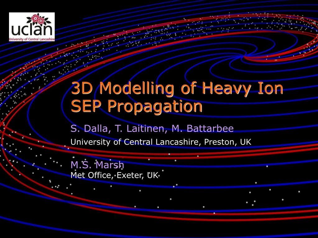
3D Modelling of Heavy Ion SEP Propagation S. Dalla, T. Laitinen, M. Battarbee University of Central Lancashire, Preston, UK M.S. Marsh Met Office, Exeter, UK
Heavy ion SEPs • An important probe into m/q-dependent acceleration and transport processes • Assumption that heavy ions propagate in 1D is a key foundation of interpretations • This talk: propagation of heavy ion SEPs is 3D
Time variation of Fe/O ratio Tylka et al, 2012
O at double average E Mason et al, 2006
Fe/O: O at double average E Mason et al, 2006
Fe/O decay interpretation • Mason et al (2006) concluded that Fe/O decay is a result of interplanetary transport, and not a signature of acceleration process • 1D modelling with a rigidity dependent mean free path can reproduce the effect (Scholer et al 1978, Cohen et al 2005, Mason et al 2006) • Exponent a related to turbulence power spectrum
Energy dependent charge states Möbius et al, 1999
Fe charge states • Within a 1D model, measured Q at 1 AU reflect source properties Popecki et al, 2003
<Q> vs E interpretation • Increase in <Q> with E as signature of acceleration process (Barghouty & Mewaldt 1999, Ostryakov et al 2000) • Energy dependent escape from acceleration region Barghouty & Mewaldt, 1999
3D full orbit propagation code • Integrate test particle trajectories in specified magnetic and electric fields (Dalla et al 2005, Marsh et al 2013) • Effect of small scale turbulence implemented as ‘ad-hoc scattering’ according to mean free path l
Simulation 1: Fe ions with multiple Q • 1.4 million Fe ions • Power law spectrum in [10,400] MeV/nuc • Unipolar Parker spiral • Constant l=1AU(rigidity independ.) – no scattering across field • 6°x6° source at latitude=20°
Fe propagation Q=20 Q=16 Q=12 Q=8 z y x rxy
Guiding centre drifts • Sum of Parker spiral gradient & curvature drifts: q =colatitude • Complex dependence on r and q Dalla et al, 2013
Fe intensity profile at 1 AU 10-100 MeV/nuc
Fe intensity profiles 10-100 MeV/nuc
Energy distribution of charge states Dalla et al, ApJ, in press, 2016
Fe and O intensity profiles Fe and O both at 10-30 MeV/nuc
Fe/O ratio Dalla et al, A&A, in press, 2016 Fe and O both at 10-30 MeV/nuc
O at double average E compared to Fe Fe at 10-30 MeV/nuc; O at 30-50 MeV/nuc
Fe/O for O at double energy Fe at 10-30 MeV/nuc; O at 30-50 MeV/nuc Behaviour observed experimentally by Mason et al (2006)
Conclusions from Simulation 2 • Within a 3D propagation model, drift to a not well-connected observer produces Fe/O decaying in time • The effect disappears when the comparison and ratio calculations are done for O at double the average energy of Fe (as observed by Mason et al (2006)) • Within our simulation this results from the dependence of drift velocity on mE/q
Shock-like injection region • Effect of variation of SEP acceleration efficiency along shock front • Latitude dependence of drift velocity • Overall 3D propagation will ‘process’ the injection properties
Conclusions • Propagation of heavy ions is 3D, due to drift and deceleration effects (Dalla et al 2015) • 3D drift-associated propagation qualitatively reproduces two key heavy ion observations: energy dependence of <Q> and time dependence of Fe/O ratio
Fe locations at t=20 hr y Q=20 Q=16 Q=12 Q=8 z x rxy rxy
SPARX SPARX: Solar PArticle Radiation swX (Marsh et al, 2015) SPARX outputs: SEP flux profiles for E>10 MeV and E>60 MeV E20 W20 W60
SEP propagation in Parker spiral l=0.3 AU l=1 AU l =10 AU
SEP Fe propagation • Fe at 100 Mev/nuc • t=100 hrs Q=20 Q=15 Marsh et al, 2013
1 AU view Map of fluence through 1 AU sphere Marsh et al, ApJ 2013; Dalla et al , JGR 2013
Energy change • Inject monoenergetic populations with initial kinetic energy K0=1, 10, 100 MeV and 1 GeV • Strong deceleration observed after 4 days Dalla et al, 2015
Time dependence • Fast deceleration during the first ~20 hours • Deceleration is present also in the scatter-free case Dalla et al, 2015
Dependence on mean free path Dalla et al, A&A, 2016